A related question is a question created from another question. When the related question is created, it will be automatically linked to the original question.
If you have a related question, please click the "Ask a related question" button in the top right corner. The newly created question will be automatically linked to this question.
Could you please give me your advice regarding all questions of TAS5538 which I have already posted since I need to inform our customer of our opinion during this week? Your quick response would be greatly appreciated.
Could you please tell us the operation of the input/output automute delay in detail regarding the automute control register(0x14)? We believe that this operation means that TAS5538 detects the audio source level less than the automute threshold level, the time before starting the automute mode is the automute delay. Is our understanding correct? In addition, is the automute operation canceled if detecting the audio source level more than the automute threshold level during the automute delay?
Could you please tell us the behavior of VALID pin in the input and output automuto mode? The VALID pin is kept high when TAS5538 detects the input automute. On the other hand, the VALID pin is asserted low when TAS5538 detects the output automute. Are those behaviors of VALID pin correct?
Could you please tell us the different between enable and disable of all channel automute timeout in detail if the DAP automute is enabled in the register 0x04?
Thank you for the information regarding the location of the input and output automute. I am looking forward to hearing from you about the remaining items.
Do you have any updates regarding the remaining questions as below?
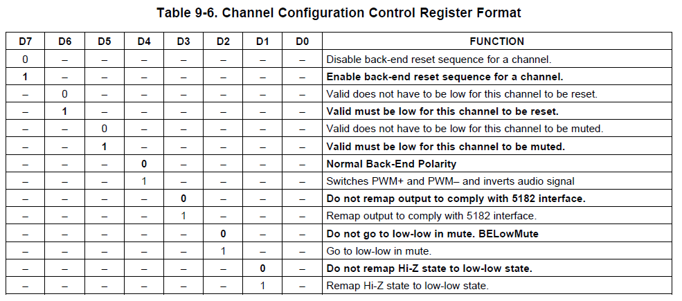
Q1. TAS5538 Channel Configuration Control Registers(0x05 to 0x0C) Could you please tell us the function of D0 register in the register 0x05 to 0x0C as below?
Q2. TAS5538 Operation of Channel Group Could you please tell us the different between enable and disable of the channel group(the D5 register) in detail if the DAP automute is enabled in the register 0x04?
Q3. TAS5538 Different Between Enable and Disable of All Channel Automute Timeout Could you please tell us the different between enable and disable of all channel automute timeout(the D6 register) in detail if the DAP automute is enabled in the register 0x04?
Q4. TAS5538 Conditions which VALID Pin is Asserted to Low Could you please tell us all conditions that VALID pin is asserted to low for TAS5538 ? We understand those conditions as below. During RESET During PDN During BKND_ERR During Output Automute
Q5. TAS5538 Behavior of VALID pin in the Input/Output Automute Mode Could you please tell us the behavior of VALID pin in the input and output automuto mode? The VALID pin is kept high when TAS5538 detects the input automute. On the other hand, the VALID pin is asserted low when TAS5538 detects the output automute. Are those behaviors of VALID pin correct?
Q6. TAS5538 Input/Output Automute Delay Could you please tell us the operation of the input/output automute delay in detail regarding the automute control register(0x14)? We believe that this operation means that TAS5538 detects the audio source level less than the automute threshold level, the time before starting the automute mode is the automute delay. Is our understanding correct? In addition, is the automute operation canceled if detecting the audio source level more than the automute threshold level during the automute delay?
Q1 - Please don't use the settings for register, except for bit D7 and D4. This is for very old power stages TAS5110, etc. Which we don't support anymore. This should be deleted in the data sheet. You can check the latest TAS5558, these are reserved. When fault pin from power stage is connected to the back end pin, the modulator has a sequence of turning it off and on for pop. I highly recommend keeping this bit (D7) enabled. Bit D4 should be self-explanatory.
Q2/3 - I have to check bits D5 and D6 to make sure the functions.
Q4 - Valid is only asserted (high) when: Reset-de-assert, PDN-de-assert, BKND_ERROR-de-assert, Automute-de-assert.
Q5 - Yes, that is correct.
Q6 - It is the time when the threshold is reached (detected) to when valid is either asserted or de-asserted. Your understanding is correct.
D5-Channel group ... there are four channel groups 1(ch1, ch2, ch7), 2(ch3, ch4), 3(ch5, ch6), 4(ch8). The intention was to establish each auto-mute threshold for each of these group. The "disable" means no group. So whichever channel has lower threshold will go into auto-mute. The "enable" means, each group will have different threshold. This function was not implemented in TAS5538. The register should have been reserved.
D6-All-channel auto-mute timeout disable ... this function also was not implemented in TAS5538. The intention was to implement an auto-mute in the PWM block. And this bit can disable or enable the automute time in PWM block. So bit D6 is also reserved.
Please allow me to ask you additional questions which I obtained from our customer as below.
1. When Asserting D6 and D5 of the register 0x04 to high How does TAS5538 work if the D6 and D5 of the register 0x04 is asserted to high?
2. When Asserting the reserved bits of the register 0x05~0x0C to high How does TAS5538 work if the reserved bits of the register 0x05~0x0C is asserted to high, except D4 and D7?
3. When Asserting D1 of the register 0x05~0x0C to high How does TAS5538 work if the D1 of register 0x05~0x0C is asserted to high? The noise occurs during the reproduction of the low frequency data if the D1 is asserted to low in the BD mode. However, that noise is improved if the D1 is asserted to high and the value of the register 0x38~0x03F which is 8 interchannel channel delay registers is adjusted. Could you please tell us that technical operation mechanism?
We are facing at a big complain from customer since our response is extremely slow.
We need to update cutomer by tomorrow so please help us to proceed the case otherwise there would be no way that we say US site is shut off now due to xmas holiday period.
Could you please update regarding the following questions since I have to reply the information to our customer by January 5(JST)?
1. When Asserting D6 and D5 of the register 0x04 to high How does TAS5538 work if the D6 and D5 of the register 0x04 is asserted to high? Is my understanding correct although I believe that nothing changes?
2. When Asserting the reserved bits of the register 0x05~0x0C to high How does TAS5538 work if the reserved bits of the register 0x05~0x0C is asserted to high, except D4 and D7?
3. When Asserting D1 of the register 0x05~0x0C to high How does TAS5538 work if the D1 of register 0x05~0x0C is asserted to high? The noise occurs during the reproduction of the low frequency data if the D1 is asserted to low in the BD mode. However, that noise is improved if the D1 is asserted to high and the value of the register 0x38~0x03F which is 8 interchannel channel delay registers is adjusted. Could you please tell us that technical operation mechanism?
Hello Kato-san,
Happy New Year. Sorry, I was on vacation and couldn't answer your question sooner.
1. As mentioned in previous post, these should be reserved registers since the function was not implemented. The designers may have used it for interal parameters or other uses. Please do not change the default settings. It may not affect anything. However in some conditions, the designers may use them for internal usage.
2. Again, reserved bits should not be altered. Please keep the default settings.
3. This bit is also reserved. In transition from TAS5508C to TAS5538, the designer may have used it for internal usage and is not meant for the customer's usage. Please keep this in default setting.
Best regards,Tuan
Happy New Year. Thank you always for your kind support. Could you please share more detailed technical information if possible since our customer does not readily understand regarding Q1 and Q3?
I have discussed with our customers based on your response, this issue has been closed. However, I will post an additional question since I have obtained a new question from them. I greatly appreciate your cooperation.