This thread has been locked.

If you have a related question, please click the "Ask a related question" button in the top right corner. The newly created question will be automatically linked to this question.

Unused op-amp in RC4558P

Other Parts Discussed in Thread: RC4558, UA741

I have a circuit with one unused op-amp in a dual RC4558P. It is single supply from a 9V battery. I noticed the unused op-amp had all three pins left floating.
In order to minimise current consumption, I connected it up as described here -

http://e2e.ti.com/blogs_/archives/b/thesignal/archive/2012/11/27/the-unused-op-amp-what-to-do

i.e. as a follower with 4.5V on the non-inverting input.

The current consumption actually increased by 1.4mA.

Furthermore, if I instead connect the non-inverting input of the follower to 0V or to 9V, the current consumption goes back down again.

Is the rise in current consumption to be expected in this "best practise" configuration?
If so, is there a better way to connect an unused op-amp to minimise current consumption?

  • Pual,

    Every op amp is different so the 'best method' for least chance of problems as seen in blog doesn't always give the lowest ICC.

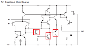
    For low ICC keep the red transistors off. This is output 'railed' high (use no load of course).

    Note in drawing that input labels are swapped. Try IN+ to VCC+ and IN- to VCC- should provide low ICC. Both inputs to VCC+ should be slightly lower ICC. You could switch to uA741 which per RC4558 data sheet front page is the single version of this device.