This thread has been locked.

If you have a related question, please click the "Ask a related question" button in the top right corner. The newly created question will be automatically linked to this question.

TPA3118D2 FAULTZ always triggered

Other Parts Discussed in Thread: TPA3118D2

Hi,

I have a board design using a TPA3118D2 amplifier.  I have SDZ and FAULTZ separated.  I keep SDZ low on startup and then a few seconds later I pull it high (3.3V).  When SDZ is low, FAULTZ is high (5V), and it immediately swiches to low (0 V) when SDZ is switched to high.

Here is the amplifier portion of our schematic.

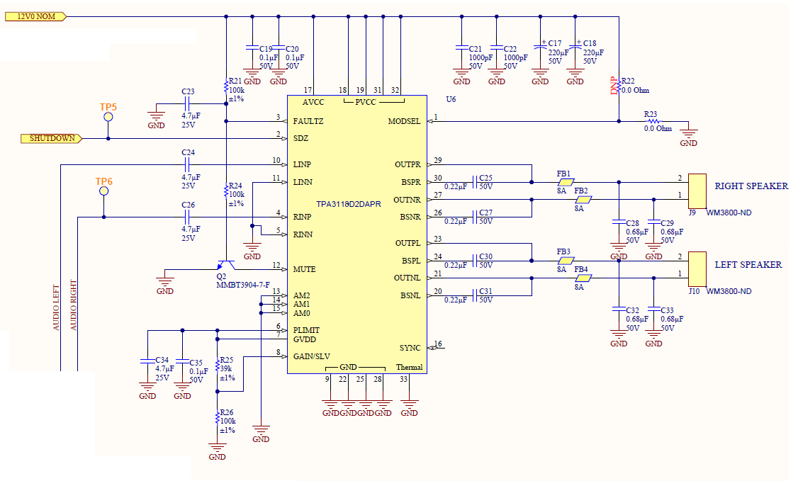
Any insight would be appreciated,

Dan K.

  • Hi Dan,

    The output filter capacitors C28 C29 C32 and C33 are too big for a ferrite bead based filter causing a short circuit fault.

    With just a small amount of combined resistance (from the output impedance and trace resistance), the 0.68uF output caps will shut the PWM switching frequency to ground causing the short circuit failure.

    This cap size is generally used with an inductor so that the inductive impedance seen by the amplifier actually increases with frequency so there is never a short to ground.

    For a ferrite bead based filter start with around 1nF for C28 C29 C32 and C33.
    For more info on Class-D Filters see here: www.ti.com/.../sloa119

    Best Regards,
    Matt
  • I modified our board to tie SDZ and FAULTZ together for auto-fault recovery.  Before making any other changes to the board I checked the FAULTZ pin on the scope.

    I then changed the caps to 1 nF and checked the scope.

    The difference is significant.  Still not quite there, but it looks to be an improvement.

    Thanks,

    Dan K.

  • Hi Dan,

    What is the scope monitoring in the above photos? Is this the output switching waveform?
    Is the device still resetting with 1nf capacitors?

    Best Regards,
    Matt
  • Hi.

    The scope is monitoring the FAULTZ pin.  The top image is before I the changed the capacitors to 1 nF, the bottom image is after I made the change.  I tried a few different capacitors in this place (2.7 nF, 100 nF, 22 pF, no cap) and saw very similar results (though I'm going from memory at this point).

    Thanks,

    Dan K.

  • Hi Dan,

    The fault pin is just a logic pin and won’t help pinpoint the problem. You need to capture the output switching waveform with a scope before shutdown. Just monitor one side of the output bridge to ground.

    You should see relatively clean square pulses. If the switching waveform is heavily rounded or triangular, the culprit is the output filter. If you are getting this with 1nF capacitors than your ferrite beads are the issue. It needs to have very low impedance in the audible band as well as at the switching frequency to allow the switching waveform to pass through the filter. If the inductor impedance is too high the pole frequency of the filter will still be to low and provide a low impedance path to ground causing OC fault. A few hundred milliohms is enough to cause this issue but not high enough impedance to prevent the OC fault.

    For the TPA3140EVM we use Murata NFZ2MSM301SN10L ferrite beads. If you look at the datasheet notice how the impedance is low until resonance. Also note that the resonance is well above the switching frequency. This is key because beyond resonance, the bead looks capacitive.

    Most cheap ferrite beads have a steady impedance climb from DC and poorly defined resonance making for poor class-D performance.
    Another test is to get a snapshot of the supply current draw before shut down. If it is high this may also point to the filter. You can also try plotting the transfer function (Vin/Vout) of your filter with a signal generator to see where the pole is.

    Best Regards,
    Matt