This thread has been locked.

If you have a related question, please click the "Ask a related question" button in the top right corner. The newly created question will be automatically linked to this question.

2.1 Loudspeaker system with multiple TAS5508C PWM modulators

Other Parts Discussed in Thread: TAS5508C, TAS5558, TAS5548

Hi,

Context:

I'm writing a project candidate for Electronics students. The goal is to design and build an audio board for a full range 2.1 audio system (stereo + sub), which is completely wireless and can play from an accu.

The demo system must be a 3way active stereo system (tri-amping) with no additional gear/enclosures, other then the speaker enclosure. Other configurations should also be possible, like a 4way and multiple subwoofers.

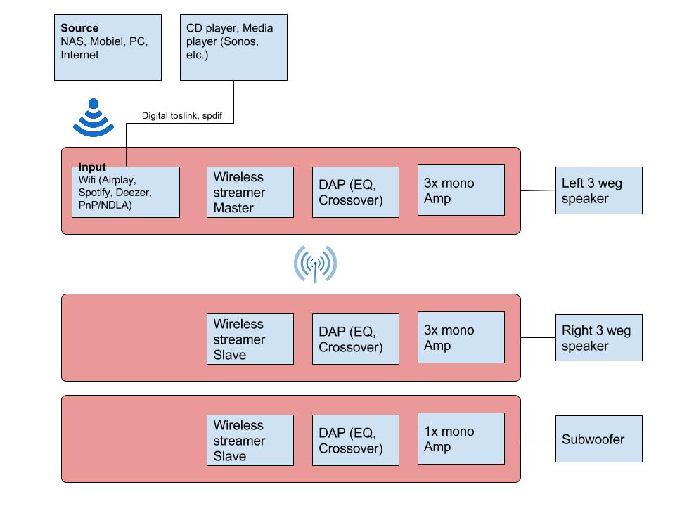
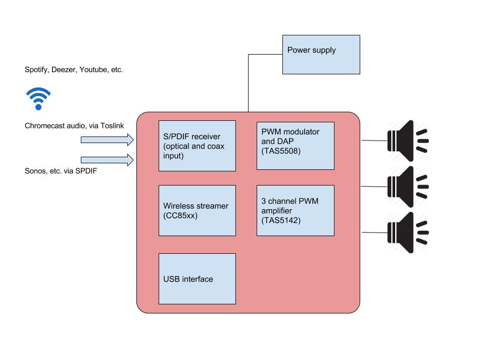
Because of these criteria, I need a very small and efficient solution. One of the solutions is a board for each loudspeaker with: CC85xx (Wireless) and TAS5508C (PWM modulator) + 51xx amp. The first board will act as a wireless master and the others as slaves. 

Question:

From what i understand is that the TAS5508C has a DAP that can be configured with the GUI software via a config file uploaded via USB. If I would have three of those boards, do I have to change the configuration on all three of them? For instance if I would make a change to the EQ or Crossover settings (biquads), do I have to update all 3 boards separately. 

any thoughts? alternative solutions?

thanks in advance!

  • Hello,

    The TAS5508C is configured through registers which are written via an I2C bus. It only supports one I2C slave address (0x36) so multiple modulators on a single I2C bus will cause issues.

    Modulators can be used on separate I2C buses without any issue but they will have to all be controlled and written individually.
    The I2C is generally controlled by the host processors and a default register setup is written to the modulator on system startup. From there, real-time adjustments to the onboard processing can be made by rewriting the registers to the desired values.
    This can be done through any means of communication between user and the host processor (GUI control, pushbuttons etc.) The register map is found in the datasheet.

    Both the TAS5548 and TAS5558 modulators support 2 I2C slave address. Therefore 2 modulates can be placed on a single I2C bus if needed.
    For a closed loop power stage with significantly better performance, the TAS56xx devices are recommended.

    Best Regards,
    Matt
  • Hi Matthew,

    Thanks!

    So if I understand correctly, the CC85xx can be the I2C master and control the other devices in autonomous or host controlled operation?

    Best regards,

    Kees

  • Hi Kees,

    Yes that is correct!

    Best Regards,

    Matt

  • Hi Matt,

    Is it possible to use only 1 PWM modulator and have the cc85xx send a PWM signal?

    Best regards,
    Kees
  • Hi Kees,

    The PWM output timing integrity of the PWM modulator is key for proper performance of the power stage. Timing for the PWM singles four Input pairs A/B and C/D on the power stage are critical. Any mismatch here can cause a lot of problems and immediate failure of the power stage if shoot through occurs (both side of the output bridge are simultaneously on)

    It may be possible to send this signal wirelessly but the resolution must be extremely high and there still needs to be a very high performance driver in front of the power amplifier for the PWM inputs.

    Honestly I don't see this working very well.

    Best Regards,

    Matt