This thread has been locked.

If you have a related question, please click the "Ask a related question" button in the top right corner. The newly created question will be automatically linked to this question.

What's Wrong with Running Bridge-Tied Load Amplifier Outputs in Series? (LM48580)

Other Parts Discussed in Thread: DRV2700, LM48580, TINA-TI

I'm trying to drive a specific sound through a piezo speaker as loudly as possible, with limited space and BOM budget.  Modelling in TINA-TI shows I would be able to drive the speaker with the LM58580 and this particular waveform at a maximum of 6.2 Vrms before sound quality starts degrading, but that's just half my target output, and the higher-output DRV2700 all-in-one piezo driver would be prohibitively expensive.  The LM48580 already contains two single-ended amps in a bridge-tied load configuration to double its voltage range from 15 Vpp to 30 Vpp.

My question is: would it be possible to run two LM48580s - or any two bridge-tied load amplifiers - side by side with identical inputs and to tie OutN on Amplifier A to OutP on Amplifier B, and connect the load (a capacitive piezo speaker) between OutP on Amp A and OutN on Amp B?  If the amplifier output pairs are floating with respect to ground, they would act like two voltage generators in series and the signal across the speaker could be as high as 60 Vpp.  This isn't the case when I simulate it in TINA-TI: the new voltage across the speaker is the same as in the single amp configuration, and the voltage across each amplifier output pair is just halved.

What's going on, and why is the output limited like this?  I'm a mechanical engineer so I'm not that well-versed on the limitations of silicon.  Are the output rails not free-floating as I'm expecting them to be (maybe constrained between 0 and 30 V relative to ground)?  Is what I'm attempting to do with two small bridge-tied load amplifiers impossible, and should I just build my circuit from discrete ampliiers and boost converters rather than limiting my search to monolithic piezo drivers?

Edited to add pics:

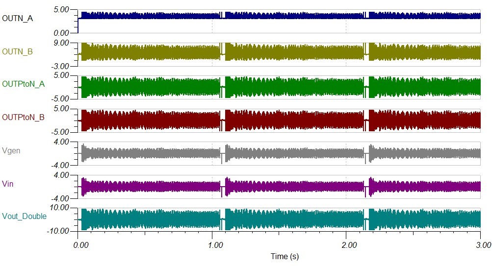
Double operation:

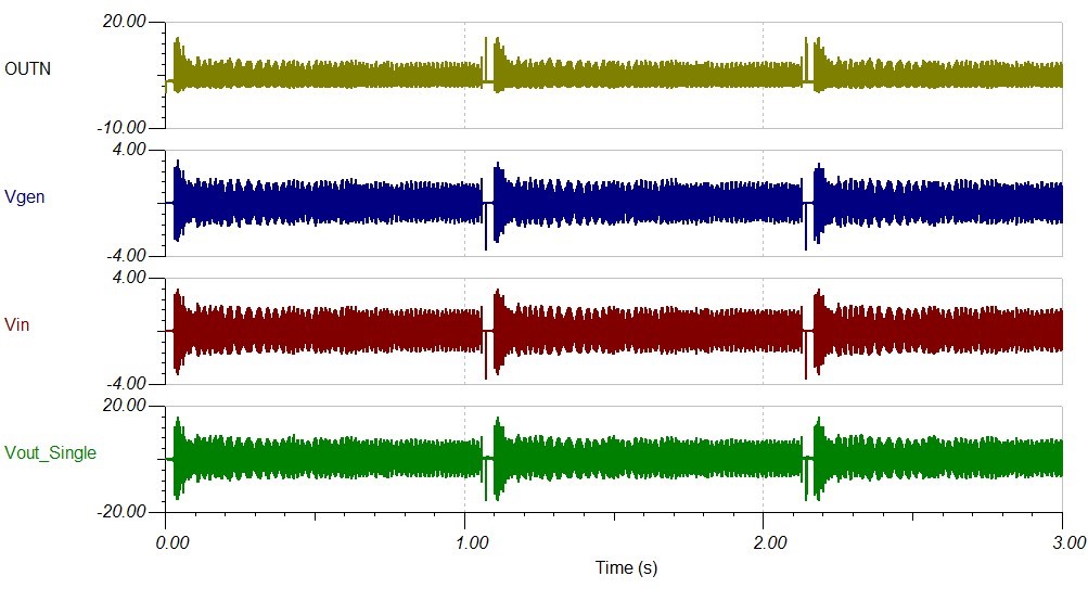
Single operation:

  • Hi Michael,

    Welcome to e2e
    The LM48580 has differential input and output (BTL output). You're grounding INN so you're actually using only the half of the dynamic range of the amplifier. Connecting the load between OUTP from AmpA and OUTN from AmpB is similar to use the full dynamic range of a single LM48580.
    This is LM48580 in Single Ended

    And this is LM48580 in Differential

    I hope this answers your questions. Let me know if you need further support.

    Best regards,
    -Ivan Salazar
    Texas Instruments

  • Hi Ivan, thanks for your response.

    I'm not having a problem getting the full 30 Vpp output range of a single LM48580 with the proper input amplitude and gain setting:  I reconstructed your single-ended configuration example and was able to reproduce your output  a 1 Vpp 200 Hz sine wave input, but I could use the same circuit to produce the output from your differential configuration by doubling the gain or input voltage.  The input DC blocking capacitors in the circuits let INP and INN float with a DC bias of around 1.2 V, so the chip still sees a differential input in both of your circuit configurations.

    What I'm trying to do is use two LM48580s (in whatever configuration) to drive a 60 Vpp output signal across the load.  I haven't been able to get it to work in TINA-TI and it looks like the output rails of each chip might be constrained between 0 and +30 V w.r.t. ground, and I'm wondering if there's a way around this.

    Thanks,

    Michael

  • Hi Michael,

    LM48580 is rated for 30 Vpp output voltage.
    I can't see any way that LM48580 could be able to provide 60 Vpp. If you connect two LM48580 parallel, like some kind of PBTL connection, it won't double the output voltage range.
    You may need a higher voltage device to get higher output voltage range.

    Best regards,
    -Ivan Salazar
    Texas Instruments