This thread has been locked.

If you have a related question, please click the "Ask a related question" button in the top right corner. The newly created question will be automatically linked to this question.

TPA3255: Issue When Using PBTL Mode

Part Number: TPA3255
Other Parts Discussed in Thread: TPA3251EVM, , TPA3245, TPA3251

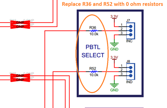
My customer is seeing the following issue when using the TPA3255EVM:

I am having an issue with a TPA3255EVM board purchased recently. It is not working as expected in PBTL mode. It appears to be entering a CB3C over-current fault as the input level approaches the point when one would normally start to see some activity on the OTW pin. The outputs shut down temporarily and then it restarts. The EVM works perfectly in stereo BTL mode all the way into hard clipping.

I am using the EVM with no modifications except re-configuring the jumpers per the table in section 3.2 of the EVM guide. I am using a 4 ohm resistive load and running the board at 36 Volts from a big HP analog power supply and supplying it with a 1kHz signal from a high quality signal generator. I have rechecked everything at least a dozen times.

BTW, I also have a TPA3251EVM operated under the same conditions and it works perfectly in both stereo BTL and PBTL modes to full power.

Here are a couple of scope shots;

The image tpa3255evm_1 shows several shutdown/recover cycles. The top trace is the power supply input current measured across a 10 mOhm shunt. The 2 and 3rd are outputs A-C and B-D to a 4 ohm resistive load. The bottom trace is the input signal. The second trace is a zoomed version of the first.


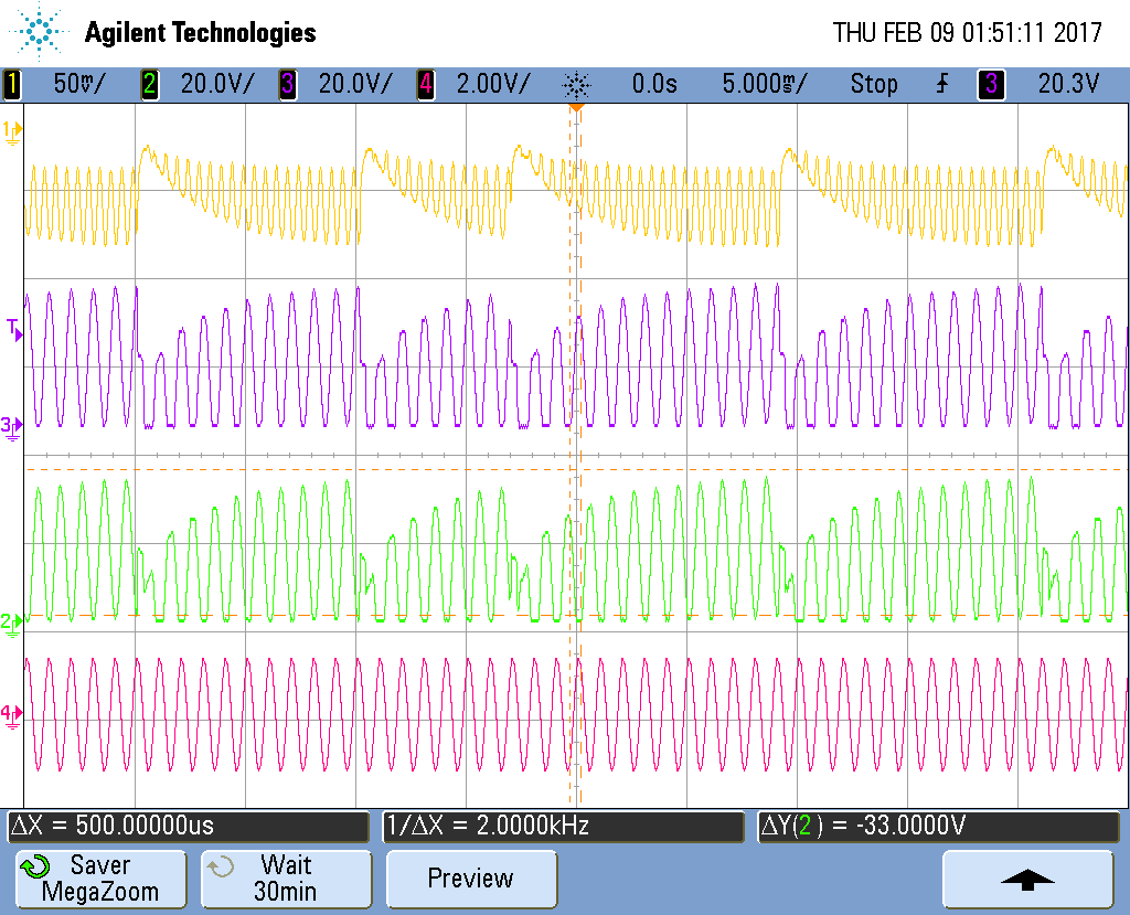
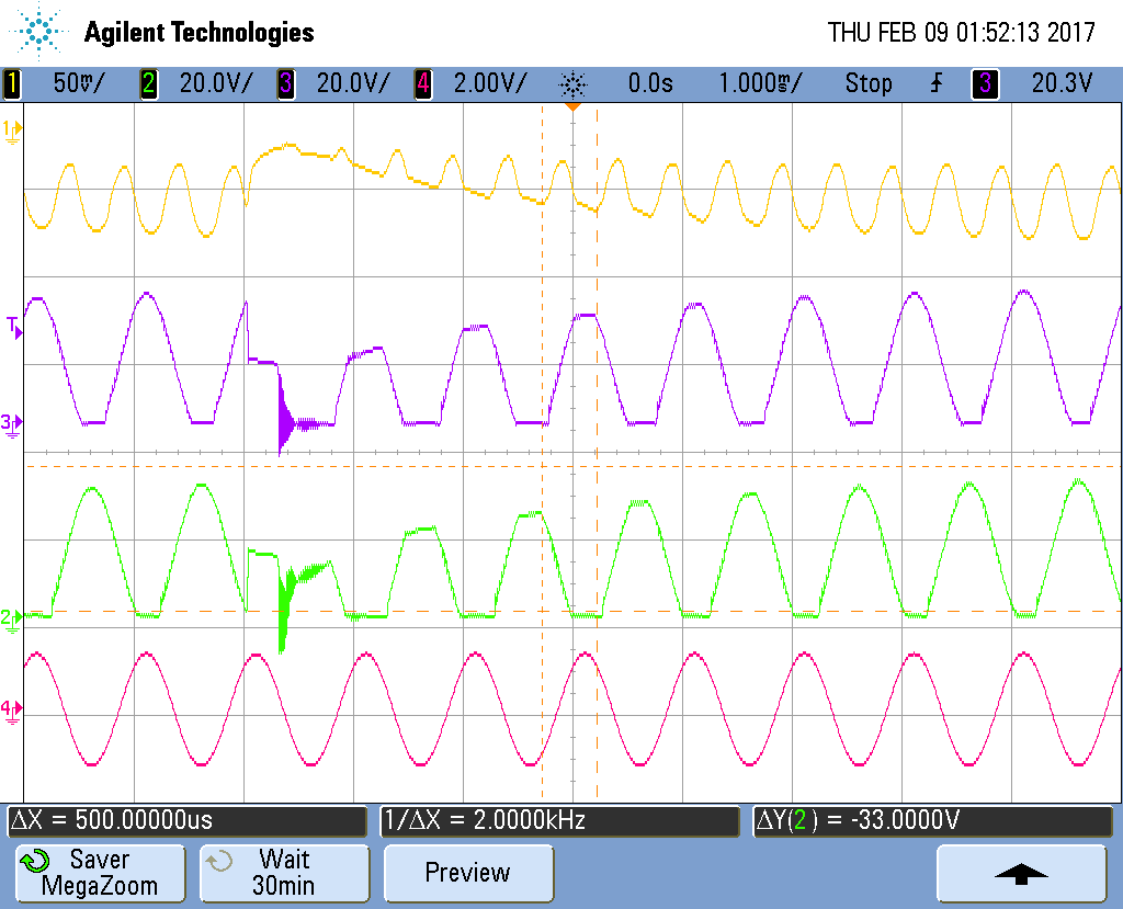
I forgot to mention that there are no signals on the OTW or Fault lines. Both are high.

I double checked everything in table 6. I have done so half a dozen times already. It still operates the same.

Based on the indicators (no activity, both hi). I thought it was the unbalanced O/C speaker protection (section 9.4.1.3) not a temperature warning. The CLIP/OTW pin shows when the outputs start clipping which is what I referred to in my original email.

Please let me know if you have any further questions for the customer.

Thanks for your help with this!

Richard Elmquist

  • Richard,  

    The EVM requires a small modification after which it will perform as expected.  I have attached pictures which detail the modification.

    These are located underneath the heatsink.

    Alternately, this can be done on the underside of the EVM without removing the heatsink, by shorting one end of both C63 and C55 to ground.  This second option is a little quicker/easier to do.

    The 10k resistor was intended as a pulldown resistor, however we found that on the TPA3255EVM there was a voltage that builds up across these resistors, which causes problems in channels C & D while set in PBTL mode. We performed the second modification on our EVM in the Lab and it solves the problem. New TPA3255EVM will have these resistors replaced with 0R resistors.  

  • Steve,

    Thanks for all your help!

    Richard Elmquist

  • My pleasure Richard. Let me know if I can help with anything else.

    best regards,
    -Steve Wilson
  • Steve,

    Your solution solved the issue for the customer but they have some additional questions:

    1.    Since the TPM3251EVM and TPA3255EVM have the same circuit connected to the C/D inputs, it would suggest that the "noise" originates inside of the TPA3255. Is this a correct assumption?
    2.    In the solution shown in https://e2e.ti.com/support/amplifiers/audio_amplifiers/f/6/t/574760 the rev. changes proposed to the EVM  only mentions changing R36 and R52 to 0 ohms on the EVM. Why are the capacitors C55 and C63 grounded in the aforementioned mods? It seems redundant unless the C/D inputs are extremely sensitive to external noise.  Will there be additional jumpers to ground those capacitors in the new EVM rev. ?
    3.    Section 10.2.4 "Typical Application, Differential (2N) PBTL"  in the TPA3255 data sheet shows a 2 inductor filter circuit instead of 4 inductors used in the EVM. Does the issue found make this configuration "iffy"?
     
    Thanks for your help with this!
     
    Richard Elmquist

  • 1.  All future TPA32xx EVMs will have this change,  not just the TPA3255EVM. 

    The TPA3251 EVM has the same problem,  however the noise from the output switching is lower (because the PVDD is lower) and thus the induced noise is not enough to cause a problem in the TPA3251evm,  if that 10k resistor was 12k or 15k,  or if the layout was not done properly,  their could be a problem with the TPA3251 also.  Thus our recommendation for the TPA3245, TPA3251 and TPA3255 is to ground these inputs directly for PBTL mode. 

    2.  This is redundant.  We do not suggest that anyone do both of these modifications.  Replacing R36 and R52 with 0 ohm resistors will solve the problem.  our suggestion of grounding C55 and C63 is an alternate solution that does not require removing the heatsink. 

    I recommend that a customer replace R36 and R52 with 0 ohm resistors,  however... if they do not have access to an SMD rework station or are in a rush.  the second option accomplishes the same thing. 

    3. The TPA3255, TPA3251, and TPA3245 can be used in with Pre-filter PBTL (2 inductor)  or post-filter PBTL (4 inductors).  The problem mentioned in the previous thread ( https://e2e.ti.com/support/amplifiers/audio_amplifiers/f/6/t/574760 ) will happen in either configuration on the TPA3255 EVM.   Both configurations are approved and supported by TI.  There are 3 main reasons for the two different PBTL configurations.   

    A: The performance is better with pre-filter PBTL given similar performing inductors.   the performance in post filter PBTL is still very good, but for applications where performance is critical,  pre-filter PBTL gives lower THD. 

    B: Using fewer inductors may lower the BOM cost.  We have found this to be true with the TPA3251 and tpa3245  However in the TPA3255,  at 2 ohms,  the peak current could approach 30A  and such large inductors tend to be very expensive and large.  So we have heard some customers say that it is still cheaper for them to use 4 inductors.  A compromise would be to use 2 inductors in parallel for pre-filter pbtl.  so each inductor saw half of the current.  This would help the customer achieve the best of both worlds.   

    C: There are some cases where a customer may be using 3-4 TPA32xx devices in one product,  and they only want to use one half of the device to drive a 4 ohm load.  In this situation,  the customer can use Pre-filter pbtl, and they will have the same THD performance, but the efficiency of the device will be better both from a power loss and thermal dissipation perspective.  

    I hope that helps to clarify.  please let me know if you have any additional questions.

    best regards, 

    -Steve Wilson

  • Steve,

    Thanks so much fro your response!

    I hope that will answer all of the customer's questions.

    Have a great day!

    Richard Elmquist