This thread has been locked.

If you have a related question, please click the "Ask a related question" button in the top right corner. The newly created question will be automatically linked to this question.

TAS5414B-Q1: DC level at input pins

Part Number: TAS5414B-Q1

When the power is turned on, the inputs of the chip have a constant voltage of 4.4V independently or not.
According to i2c:

step 1
  I read registers 0x05 in response 0x0F
I read registers 0x06 in response 0x00
I read the registers 0x0c in response 0x1f

step 2

I write in 0x0с first 0x10 then 0x0f.
I read the registers 0x0c in response 0x0f
I read registers 0x05 in response 0x0F
I read registers 0x06 in response 0x00

step 3

I write in 0x0с first 0x10 then 0x00.
I read the registers 0x0c in response 0x00
I read registers 0x05 in response 0x0F
I read registers 0x06 in response 0x00

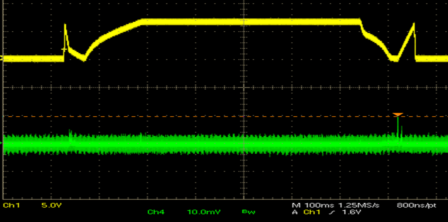
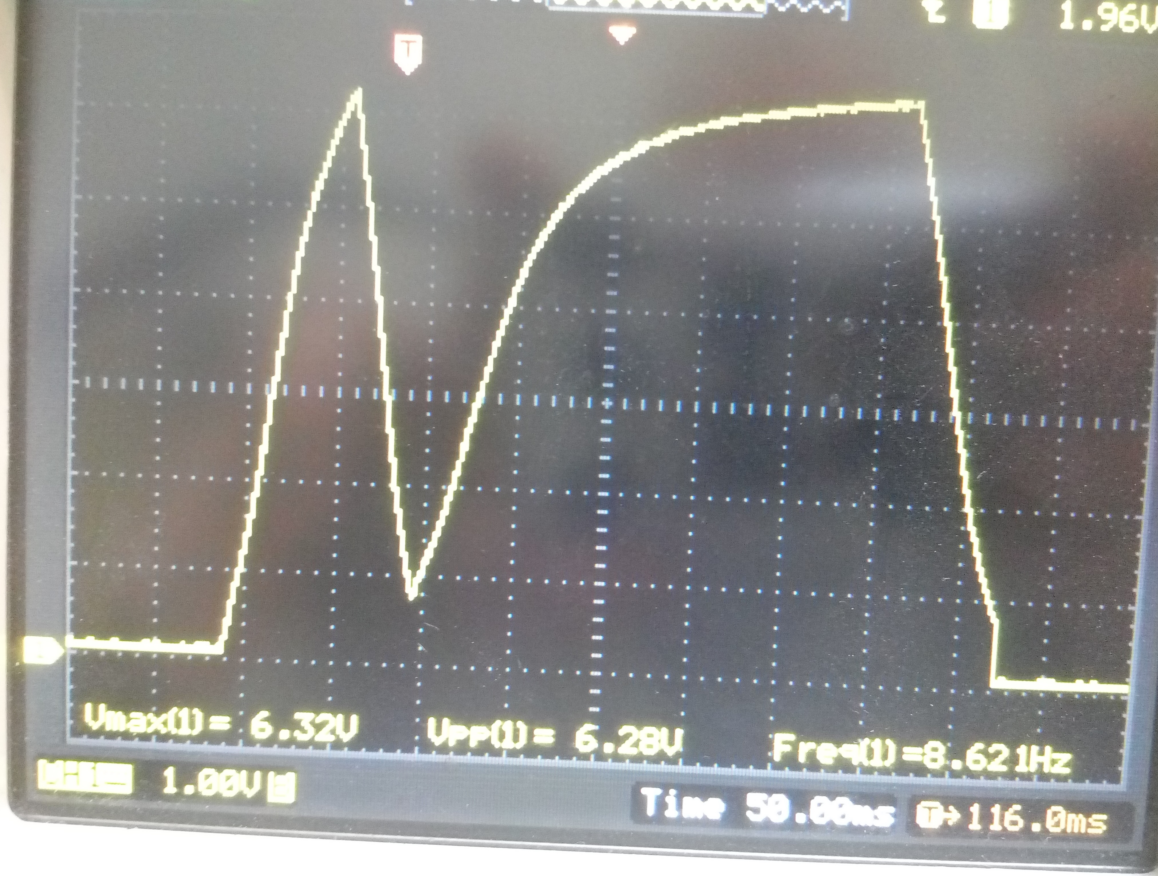
At the MUTE pin, only a 0.2 μF capacitor is connected. There the oscilloscope shows only 1.08 Volts.
The standby input is pulled up to 5 Volts.
What do I do wrong to turn on the playback mode?

  • Ivan,

    There seems to be a voltage problem on the MUTE pin.  It should be a 0V when in Hi-Z and MUTE modes.  And 6.8Vdc when in Play mode.  If it is stuck at 1.08 Volts then something is holding it there.
    Check the MUTE pin on the oscilloscope when you change the values of registers 0x0C.

  • Hi, 

    I found a mistake in myself, conclusions 7,8,9 were not connected to the ground.
    After connection, the level at the MUTE pin dropped to 0V.
    But as before, there are no changes when writing to the 0x0C register, it is not displayed in the registers 0x05 and 0x06.
    And the sequence is correct when writing to the 0x0C register:
    First 0x10, pause, then 0x00?
    Also, nothing changes if you look at the Mute output of an oscilloscope.
    Is it normal that the inputs have DC voltage, even if they are disconnected?

    Regards, Ivan

  • Ivan,

    The Mute pin should have a waveform like shown in the figure below.  The left side is they turn on waveform, the right side is the turn off.

    The maximum voltage is 6.8Vdc.  The time base is 100ms per division.  If you do not see this occur, something is holding down the mute pin.  The turn on cannot progress if it is being held down.  It must be allowed to charge the discharge the 200nF capacitor on the mute pin.

  • Hi

    I found a change to the MUTE output, only when writing to 0x0B.
    For example, when I'm trying to write a value 0h4F or 0h5F. In this case, the voltage of 6.8 volts per 100 msec appears on the MUTE pin and again drops to 0.

    If the register is immediately counted as 0x0B, then 0x4F is written with 0x40, and with the value 0x5F.


    You also did not answer about the constant voltage at the inputs, this is normal, can the chip not be working?

  • Ivan,
    Writing to register 0x0B a value of 0x4F or 0x5F you will see the load diagnostics run. The load diagnostics uses the Mute Capacitor to run Open Load and Shorted Load diagnostics. This is good information, because I can see that the pin is allowed to go to 6.8V per my previous replies. Do you read register 0x02 or 0x03 for the diagnostic results?

    Can you get the Mute pin to look like the above oscilloscope picture? Write 0x00 to register 0x0C and you should see the left side of the yellow trace. If you write a 0x10 to register 0x0C, you will see on the first rise and fall of the yellow waveform.

    The input pins need DC to be correctly biased with a single supply. The TAS5414B-Q1 provide this internally and you will measure around 3.6Vdc on these pins.
  • Gregg,

    When I write to the 0x0C register 01 or 00, nothing happens to the MUTE outputs. In this case, reading the values 0x02 and 0x03, I get 0x00 in response.

    As soon as I turn on the output diagnostics (register 0x0B), I see changes on the output of the MUTE (see attachment).

    After changing the value of register 0x0B, I read the values from the register 0x02 and 0x03 and get 0xAA in response (this is if the outputs after the filter are not connected).

  • Ivan,
    The oscilloscope shot looks about right. The value of 0xAA from 0x02 and 0x03 should not occur, only 1 bit per channel can be set at a time.
    Are you using your pcb or a TI EVM? What are you using to communicate with the TAS5414B? Our I2C pcb or your I2C controller? I am thinking that maybe you have an I2C communication issue.
  • Gregg,
    I use the converter UART-I2C SC18IM700. To write to the register 0x0С, I write the command 0x53 0xD8 0x02 0x0C 0x00 0x50. If I had errors in communication on I2C, I would not get the correct answers in other registers and I read the values that I write down.
    Why can not I get a 0xAA response from register 0x02? If I connect the load to the output 2, I get a response of 0x2A.
    I use my own pcb.

  • Ivan,
    During load diagnostics the test will stop on first fail for each channel. The values of 0xAA in register 0x02 and 0x03 means that each channel as a short to PVDD and an open load. The test would stop on the short to PVDD and not continue and not test for an open load. The value should be 0x22, if all channels are shorted to PVDD. You said it was open load, so I would expect 0x88. Basically the only valid values for each channel is 1,2,4, or 8.
    Have you verified your PCB? It seems it report a short to PVDD. It this correct?
  • Hi Gregg,

    I found the reason for this strange behavior:
    When the power is turned on, 0x74 and 0x0F are written to the 0x00 and 0x01 registers.
     And while they are not counting the chip will be in Fault mode.
    In this case, you must first read the value from register 0x00 two times until you get the answer 0x04.
    Then read 0x01 from the register the same two times until you get the value 0x00.
     And then re-read 0x00 from the register and also get the value 00 in the answer.
    Only after this, you can set the values ​​in the 0x0C register.
    Most likely I have too large electrolytic capacitors in the power circuit (2x3300mkF) and they take too long to be charged, and the logic inside the chip works at a lower voltage and has time to measure the voltage on the PVDD, and then records the error.

  • Ivan,

    It is good to know that your power supply ramp time is getting you into trouble.  You probably do not need so much capacitance on the power supply.