This thread has been locked.

If you have a related question, please click the "Ask a related question" button in the top right corner. The newly created question will be automatically linked to this question.

PCM4222EVM: Error? PCM4222EVM evaluation board.

Part Number: PCM4222EVM
Other Parts Discussed in Thread: PCM4222

hello

I own a PCM4222EVM evaluation board .

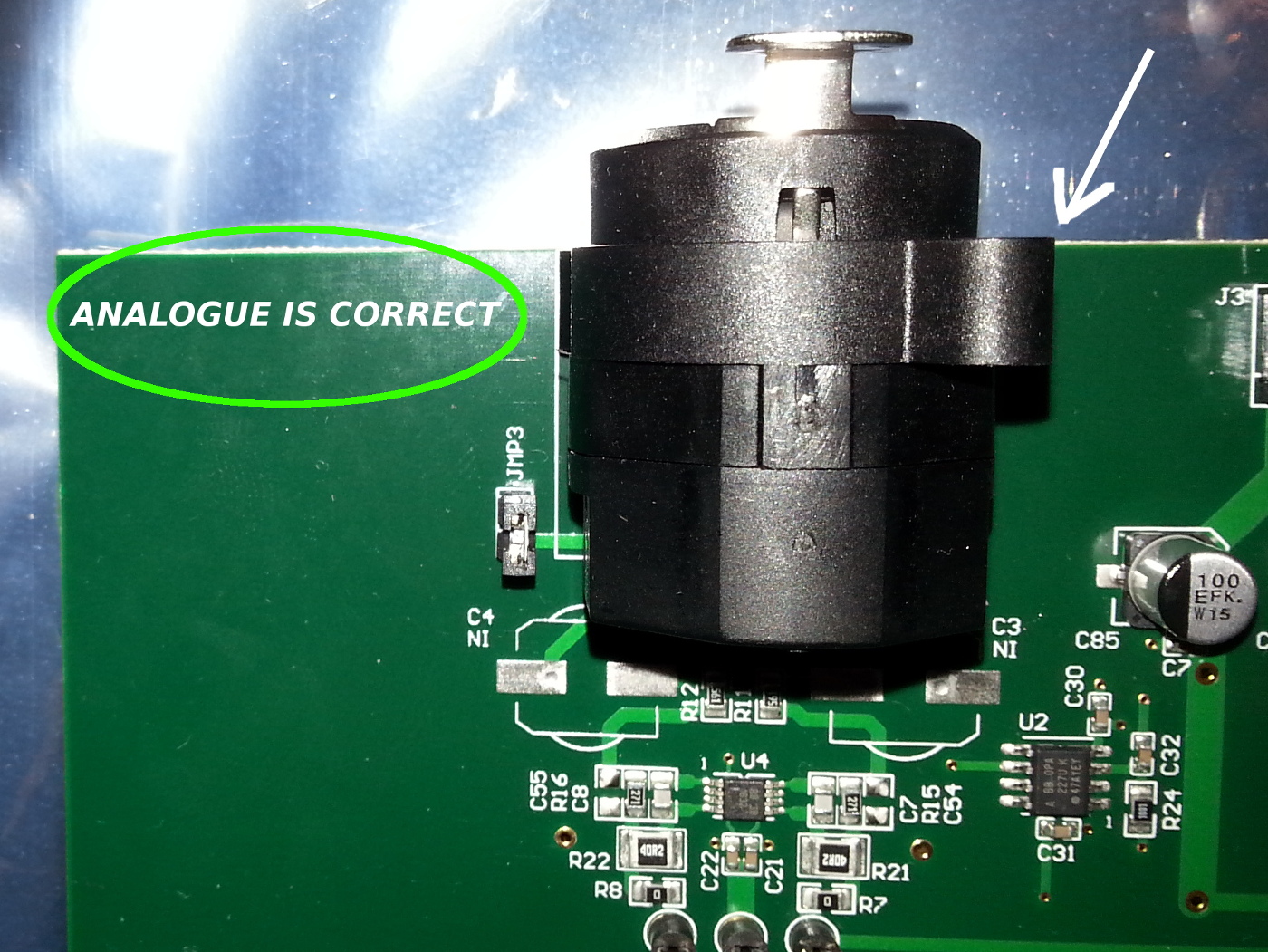
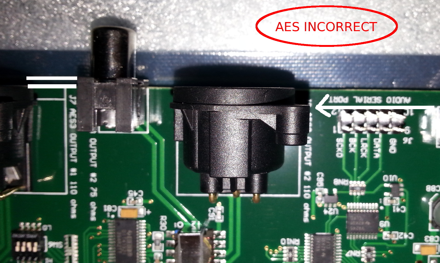
I believe from inspection that the XLR digital AES connectors J7 & J9 are mounted incorrectly at the TI factory.

The xlr's are placed too far back.  I do not think an adaptor will help as the (edit*) 'the rear panel'  would get in the way of the XLR jack; as an XLR jack needs to be flush the the AES socket to mate and click into place.

Can anyone please confirm this?  Is this an error on all versions of this board? 

Thank you.

  • Hi, Harps,

    Welcome to E2E, Thanks for your interest in our products!.

    Thanks for your comments, Can you please post a picture of the connector that you are referring to? I have verified in the EVM that the XLR connector for the AES interface fits in the EVM without issues.

    Best Regards,

      -Diego Meléndez López
       Audio Applications Engineer

  • hello Diego

    I have included two pictures

    picture 1. = the analogue XLR, this is correct.

     picture 2. = the AES XLR which is set back and means mating with a panel is not possible. If spacers are used then an XTR jack will not click into place and mate either.

    AES BELOW

  • Hi, Harps,

    Thanks for the feedback. You are right, the connectors are not properly located to make the panel mount. This board was designed a couple years back so it seems this as not considered before. The EVM is targeted to be used with cables, so the only way to mount the connectors in a panel would be by removing  them from the board and solder them with cables.

    Best Regards,

      -Diego Meléndez López
       Audio Applications Engineer

  • Hello Diego

    Regards this problem, you state:

    "The EVM is targeted to be used with cables,"

    You mean , XLR cables that plug into the AES XLR's sockets after they are mounted in a " chassis ".

    As the Texas Instruments PDF states :

    "J7 J9 = neutrik 3-Pin Male XLR Chassis Connector, Horizontal PC Mount."

    This EVM PCB was designed to be mounted in a " chassis " and to be used with XLR cables and the provided j7 j9 neutrik PCB sockets.

    However, This PCB design error prevents this from been possible and you state therefore I need to remove these
    XLR's as they are not fit for purpose, using a de-soldering tool and other parts such as solder lug chassis XLR sockets so to make it fit a chassis.

    Can you clarify this please or advice me otherwise.

    Thank you
  • Hello, Harps,

    The main purpose of this EVM is to be used as an evaluation tool for the PCM4222 Audio ADC, the connectors used on this and several other EVMs we have are selected just as a way to interact with the required cables for specific purposes. This particular Male XLR connector was selected only as a way to connect a  female XLR cable,  the Chassis mount was not a particular feature considered for the design of this EVM. Ideally, the designer of this board should have considered the proper connector footprint to allow the chassis mount, but as it was not an intended feature for the EVM, this was not done.

    Best Regards,

      -Diego Meléndez López
       Audio Applications Engineer

  • Hi Diego

    Will you update the PDF file to state that ' Although the EVM uses chassis mount XLR's, the AES XLR's and RCA ports 'cannot' be chassis mounted due to the wrong pcb XLR footprint being used. However, the analogue XLR can be chassis mounted.' ?

    Might make all this worth our time and save other people time too.

    Thanks for your time
    kind regards.
  • Further to above

    TI quote:

    " The PCM4222EVM provides a complete environment for evaluating the functionality and performance of the PCM4222
    integrated circuit." "J7 J9 = neutrik 3-Pin Male XLR Chassis Connector, Horizontal PC Mount."

    Gave the impression that one could have a shielded and safe environment for the EVM, to chassis mount the AES and be able to move the EVM from location to location to demonstrate it to others in a chassis. (no mention of a required de-soldering tool to remove a wrongly installed chassis mount XLR)

    The PDF should be updated to be fair. that "This is for a work top unshielded environment only. and not designed to be chassis mounted."
  • Harps,

    Thanks for your feedback, we will consider it for the next User's Guide revision.

    Best Regards,

      -Diego Meléndez López
       Audio Applications Engineer