This thread has been locked.

If you have a related question, please click the "Ask a related question" button in the top right corner. The newly created question will be automatically linked to this question.

OPA4134: OPA4134 running really hot. (50C) is this normal?

Part Number: OPA4134

Hi, 

I recently worked on an audio line input to an A/D converter.  

The circuit seems to work properly, but I've noticed that the OPA4134 gets really hot.  

Is this normal for this opamp? or something I should change to avoid this issue. 

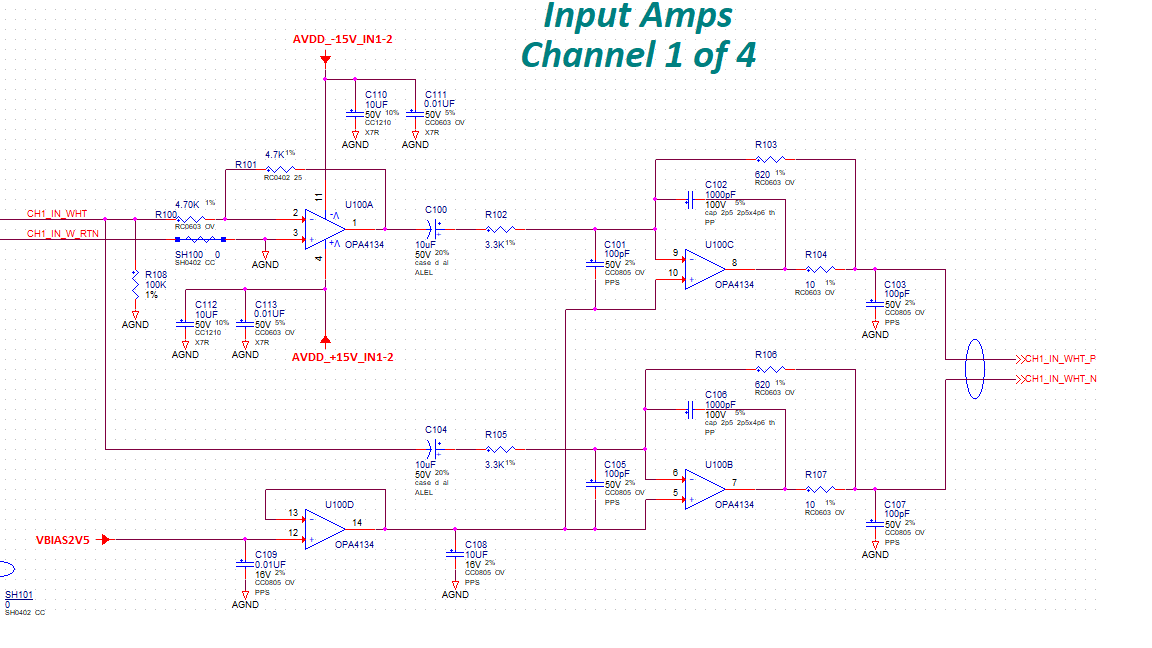
I've pasted the circuit below.  

  • Hello Sato-san,

    Check the OPA4134 output pins 1, 7, 8 and 14 for any signs of instability (oscillation). Make sure to use a a wideband DSO, with a 10 x probe.
    U100D is connected as a unity-gain buffer in the circuit and has a 10 uF capacitor connected from the output to ground. That could be an unstable load condition. If any of the amplifier sections are oscillating they may be drawing excessive current, which will cause the amplifier to heat.

    OPA4134 datasheet Figure 26, Small-Signal Overshoot vs Load Capacitance, indicates a maximum load capacitance of about 1 nF for a gain setting of +1 V/V - so 10 uF may be a problem.

    Regards, Thomas
    Precision Amplifiers Applications Engineering
  • Hi Thomas,

    Thank you for the quick response.

    I've been looking for oscillation, but so far, I have not seen any oscillation on the pins 1, 7, 8 and 14.. I've been using 100MHz DSO but no obvious oscillation, but I'll keep looking.

    Interestingly, the unity gain buffer had 1nF in the original circuit. The output of the unity gain buffer was oscillating and that was the reason for changing to 2.2uF then to 10uF.

    Instead of 10uF load, should I be inserting a series resistor or a load resistor to the circuit along with 1nF to that unity gain buffer??

    Thank you again for your help!!

    Haku Sato
  • Hello Haku,

    If the OPA4134 isn't oscillating or delivering output current to a load, then the only other possibility for generating heat is the device self-heating as a result of the quiescent power conditions. The power being dissipated by the OPA4134 is surprisingly high when the device is just sitting in a idle, in the quiescent state. Using your +/-15 V supplies and the typical quiescent current of 4 mA per op amp section the power dissipation, Pd:

    Pd = [(V+)-(V-)] Iq = [(15 V) - (-15 V)] (4) (0.004 A) = 0.48 W

    I don't have the exact junction-to-case thermal resistance number θjc, or the junction-to-ambient number θja for the OPA4134 14-pin SOIC package, but for similar devices θjc and θja are about 26.9°C/W and 66.6°C/W (Hi-K model), respectively. When I run some calculations I approximate a case temperature around 40°C, when an ambient temperature of 25°C is used. However, the actual temperature depends on how the PC board copper area and design to which the OPA4134 package is mounted. If the SOIC package leads cannot fully conduct its portion of the heat to the copper areas, or if the package can't fully radiate its portion of the heat, then the package temperature will be higher than ideal.

    A common practice to enhance stability when driving a capacitive load is to add an isolation resistor between the op amp output and the capactive load. Doing so increases the phase margin. A possible one drawback is if the an impedance is connected at the resistor capacitor output node, a voltage divider is created. That can be a problem in some applications. There is a dual feedback circuit that can be applied to restore the voltage to the correct level.

    If the series resistor (~100 Ohms) and a smaller value capacitor result in an acceptable, stable output then that is an option. You can obtain a relative check of the circuit stability by applying a small-signal (1 kHz, ~20 mVpk) signal to the input of the amplifier stage and the observing the output waveform with a DSO. Check the level of the over-shoot, or under-shoot. See the Transient Overshoot, and Phase Margin vs Percentage Overshoot figures in TI's Analog Engineer's Pocket Reference (available on line) to determine the phase margin. The R and C ca be adjusted accordingly.

    Regards, Thomas

    Precision Amplifiers Applications Engineering