This thread has been locked.

If you have a related question, please click the "Ask a related question" button in the top right corner. The newly created question will be automatically linked to this question.

PCM1754: Noise problem of PCM 1754

Part Number: PCM1754

Dear TI FAE

I use PCM1754 for DAC in my projector model, but there is some noise output from 7 pin.

here is my schematics:

PCM1754 configuration as follows:

FMT = HIGH,DEMP = LOW,Mute = LOW;


And my audio format is 16k samples,16 bit per sample, 2 channel.

when i send zero data to 1754 with I2S bus,as follows:

the pcm1754 output noise(Oscilloscope probe in DAC_VO,show in schematics above),as follows:

zoom in as follows:

Could you please help to check ASAP ?

Thanks and best regards.

  • Hi Liu,

    Can you take an image of your supply? Specifically at the DAC5V node. In addition, please capture the output of the VCOM pin. This will give us an ideal if the source is the power supply.

    Thanks!
    Paul
  • Thanks for response

    here is my DC5V power schematics as follows:

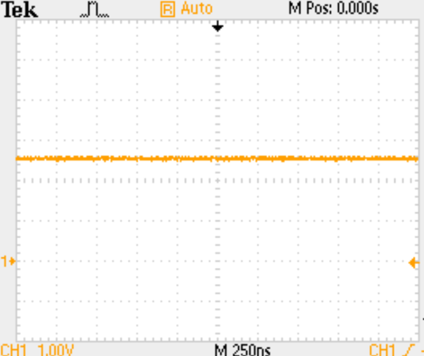
    and the output  wave of the VCOM pin,as follows:

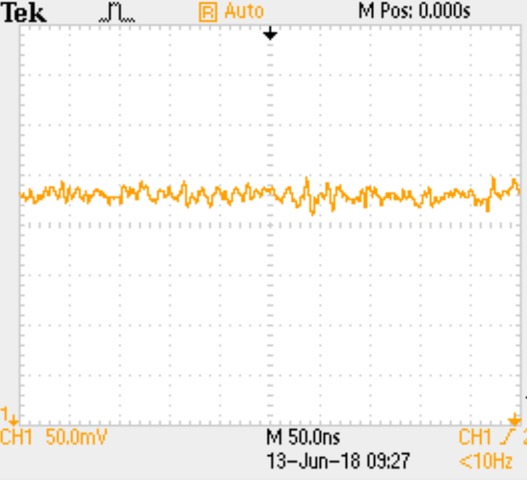
    zoom in as follows:

    Could you please help to check ASAP ?

    Thanks and best regards.

  • Hi Liu,

    The power supply looks reasonably clean. I suspect this is digital cross talk issue from the layout. What are you using as SCK? I suspect that it is 1.22MHz.

    Please take a look at your PCB layout. Do you have a good return path for ground? Are the digital signals routed away from the analog output?

    Thanks!
    Paul
  • Thanks for response.

    SCK is 8.192m HZ,

    and it`s from the mcu(external 8.192M crystal oscillator as clock source) with one frequency division.

    Thank you for your suggestion.

    We're going to layout again and test it again.

  • Feel free to share your layout review.

    Thanks!
    Paul
  • Dear TI FAE.

    Thanks for response!

    Now we made the second edition of PCB,Can you give us some advice about  the pcb(include TI PCM1754 and TI TAS5421)?

    First edition of SCH and PCB as follows(this edition has the noise problem):

    Second edition of SCH and PCB as follows:

    Could you please help to check ASAP ?

    Thanks and best regards.

  • Hi Liu,

    A few comments:

    1. The inputs to the class D should have the same impedance, so I think C44 should be the same as C49

    2. I would ensure that there is a clean path from the IN_N and the AGND pin of the PCM1754.  I looks pretty good right now, but I cannot see the bottom layer in the images.

    3. I would recommend C0G/NP0 type capacitors for the audio path capacitors and thin film type resistors.

    Other than these comments I think the design looks good.

    Thanks!

    Paul