This thread has been locked.
If you have a related question, please click the "Ask a related question" button in the top right corner. The newly created question will be automatically linked to this question.
Hi TI Experts,
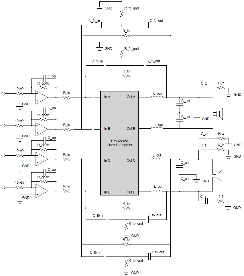
In my design I drive TAS3255 directly from PCM1795 DA converter. My D/A output low-pass filter use OPA1632 fully differential amplifier:
I would like to implement also PFFB directly in this design without using additional buffers / summing amplifiers between low-pass section and TPS3255 input. Could you tell me how to adjust / calculate the components? The component values in low-pass filter stage are taken directly from PCM1795 datasheet. Can I simple adjust PFFB components and R138/R139/R158/R159? Or I need to redesign my low impedance low-pass filter stage?
Thanks for your support, Tomasz
Hi Justin,
Thanks for your reply. I analyzed a bit PFFB application note any tried to understand the concept:
I understood, the important parameter is the feedback factor and the right change of closed loop gain. Can I just use 2k7 resistors for R138 / R139 / R158 / R159 - this is the value from the datasheet ;) Would it work also for my application?
What is the primary function of the opamp input stage? 10k / 10k suggest it is like unity gain buffer with limited bandwidth - probably for the stability reason... The R_in resistor should have any influence on the input opamp stage, shoudn't it? The most important will be the keep the right ration of R_in and R_fb resistors to keep feedback factor low and set the right closed loop gain...
Are the values in the application note calculated or estimated and than optimized doing lab measurements?
Cheers,Tomasz