This thread has been locked.

If you have a related question, please click the "Ask a related question" button in the top right corner. The newly created question will be automatically linked to this question.

PCM5100A: PCM5100A power on no audio output

Part Number: PCM5100A
Other Parts Discussed in Thread: PCM5102A

Dear TI:

    Customer used PCM5100A in product, and sometimes PCM5100A no output when it power on, but reset the power, output normal.

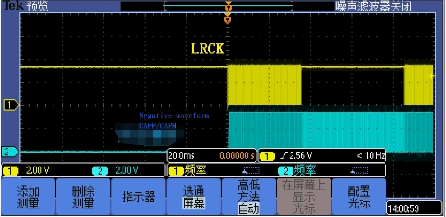
    The customer tested and found that there was no output at startup, and the PIN CAPP and CAPM of IC were abnormal, fould the  square wave, but the frequency was 880KHz, and the IC frequency of normal output was 1.5MHz. What was the reason for this abnormal?
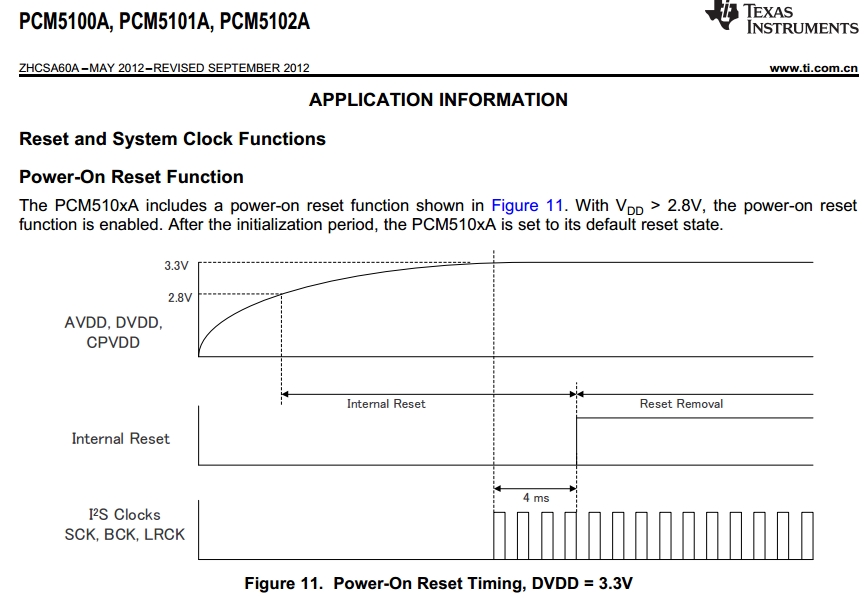
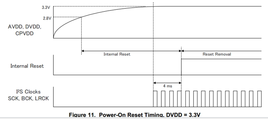
At the same time, do PCM5100A have any requirements for the power timing? At present, the customer set SCK, BCK and LRCK to output first, and then VDD power up. The data of IIS will not be sent out until the power up exceeds 10ms. Is this timing sequence OK?

  • Hi Eric,

    The PCM5100A does not configure it's clock tree until a valid clock has been applied.  It is possible that the input clocks were invalid and the clock tree was misconfigured.  The timing of the power up should not cause an issue.  In addition, the charge pump requires a 2.2uF capacitor - be careful when selecting a capacitor that has too low of a voltage rating, as most ceramic caps are de-rated when operating near the voltage limit.  

    Table 10 lists the only rates that supported in the 4-wire mode.  Note that the rates marked with (2) are not support in 4-wire mode, as the PCM5102A is hardware only device.  Table 11 shows the subset of those rates that are supported in 3 wire mode.

    Thanks,

    Paul

  • Hi Paul:
    Thanks for your reply!
    The cap of charger pump is 2.2uF/16V.
    The customer has provided more detailed information, I will update it to you, and please help check it again:
    1, In normal condition, the frequency of square wave of CAPP/CAPM is 1.536MHZ; in abnormal condition, the frequency of square wave of CAPP/CAPM is 865.68KHZ.
    2, The machine of no output when starting up,when the software turns off and then turns on the audio analog A3V3 power supply (AVDD, CPVDD), PCM5100A immediately has sound output. At this time, the frequency of CAPP/CAPM square waves becomes normal.
    Note: the digital D3V3 power supply DVDD is independently separated from the analog A3V3 power supply. At this time, the software only turns off the analog A3V3 power supply, but does not turn off the D3V3 power supply.
    3, At present, the timing sequence we tested is: D3V3 power on -- > 5.5 seconds after CPU output SCK and BCK waveform -- > A3V3 (AVDD, CPVDD) power on -- > 5.8 seconds after LRCK, negative pressure, CAPP and CAPM generation -- > DATA
    4, Related frequency
    SCK: 24.576 MHZ
    BCK: 3.072 MHZ
    LRCK: 48 KHZ
    CAPP and CAPM: 1.536MHZ with normal sound, 865.68KHZ without abnormal sound
    5, The question now is:
    1), At present, digital D3V3 and analog A3V3 are independent, D3V3 first power on,after 5.5s A3V3 power on, witch power trace is PCM5100A internal reset based on? D3V3 or A3V3??
    2). The signal of I2S is difficult to be stable according to the time in the sequence diagram, that is, it cannot be generated before the internal reset completed of PCM5100A. Can I2S signal be generated at any time after the internal reset completed of PCM5100A?
    3), Customer test failure machine, they turn off A3V3 and then turn on V3V3, the machine is normal output, so can A3V3 power on after all CLK signal output?

  • 1. The reset is actually based on both supplies. Though it recommended to use XSMT to act as a supply supervisor input. XSMT should be asserted to 0V until both supplies are established.
    2. Yes, the I2S signal can be applied at any time, before or after POR.
    3. Yes, but once again I recommend having XSMT asserted to 0V during the supply ramp.
  • Hi Paul:

      Some more questions need you help to check:

      1, From the sequence chart of below,  the reset removal is after IIS Clocks(SCK, BCK, LRCK), there are three clocks, the reset removal require  all 3 clocks output normal or only one of them output normal?

        2, The waveform below is customer PCBA CPU output, the LRCK is the last one output, when LRCK output, the CAPP and CAPM output negative waveform, the frequency is 1.532MHz.

    However, after LRCK outputs dozens of ms waveforms (at this time, the negative waveform frequency is 1.532MHz), LRCK will be pulled up by 50ms (at this time, the negative waveform frequency is about 800 KHz), and then output the normal 48KHz waveform (the negative waveform frequency returns to 1.532MHz).
    The negative voltage waveform frequency of over 800 KHz is basically the same as the negative voltage frequency we tested before when the machine power on was occasionally silent.


    Related to CPU manufacturer, this is because the FW is set to go bit, which will be set in many cases, such as before playing files, end of playing files, sampling rate or channel change, PCM /raw switch and so on. LRCK is going to be pulled up for a while.

    The question are:
    1)After all the waveforms are normally output, one CLK (such as LRCK) is abnormal (such as pulling up), and then the normal CLK waveform is restored, whether it will affect the normal generation of negative waveform from CAPP/CAPM.
    2)How long or how short will LRCK pull up affect the negative waveform frequency?


       Thanks!

    Regards!

    Eric 

  • Hi Eric,

    The PCM5102A requires both LRCK and BCK to be valid for the charge pump to operate. In section "9.3.2.1 Audio Serial Interface" it is stated that if the BCK and LRCK are out of sync for more than 4 LRCK periods, the device will stop the output and re-synchronize. If the clock is not available during the re-synchronization, the clock tree cannot be configured and the device will enter an idle state.

    Thanks,
    Paul
  • Hi Paul:

       There are two conditions that cause LRCK and system clock resynchronizate, please see the screenshot as bellow:

       How can we determine that resynchronization has completed? After resynchronization is completed, can PCM5100A output audio as normal?

       Now the problem is  PCM5100A failed to output audio at startup,  Is the reason of resynchronization incomplete?

       The customer wants to find the root cause of no sound output, please help confirm.

       Thanks!


  • Hi Eric,

    Once re-synchronization is complete, the charge pump (VNEG) will be active and go to ~-3.3V.

    Can you describe the issue at startup? Is there no output after all the clock lines are established and XSMT is high?

    Thanks,
    Paul
  • Hi Paul:
    You can refer back to the previous post, there is no output of PCM5100A when machine power on, XSMT is high.

    1, In normal condition, the frequency of square wave of CAPP/CAPM is 1.536MHZ; in abnormal condition, the frequency of square wave of CAPP/CAPM is 865.68KHZ.
    2, The machine of no output when starting up,when the software turns off and then turns on the audio analog A3V3 power supply (AVDD, CPVDD), PCM5100A immediately has sound output. At this time, the frequency of CAPP/CAPM square waves becomes normal.
    Note: the digital D3V3 power supply DVDD is independently separated from the analog A3V3 power supply. At this time, the software only turns off the analog A3V3 power supply, but does not turn off the D3V3 power supply.
    3, At present, the timing sequence we tested is: D3V3 power on -- > 5.5 seconds after CPU output SCK and BCK waveform -- > A3V3 (AVDD, CPVDD) power on -- > 5.8 seconds after LRCK, negative pressure, CAPP and CAPM generation -- > DATA
    4, Related frequency
    SCK: 24.576 MHZ
    BCK: 3.072 MHZ
    LRCK: 48 KHZ
    CAPP and CAPM: 1.536MHZ with normal sound, 865.68KHZ without abnormal sound

    Regards!
    Eric Shen
  • Hi Eric,

    Is there a specific sequence that always results in the abnormal sound? Or does it seem random or determined by how long the LRCK is missing?

    The PCM will attempt to auto-configure the clock tree based on the input input clocks. I suspect that there is enough digital cross-talk from the other lines that the LRCK is being read as a higher data rate. I am not sure if there is a simple solution to this.

    I recommend that the XSMT be held low until all the clocks are established, so the auto-detect will occur only when there are valid clocks.

    Thanks,
    Paul