Hi!
I am wondering if it is possible to configure the PCM5142 to accept TDM input where the BCK is 256*fs (8 channels with 32 bit words) through a 3-wire PCM interface (i.e. use BCK PLL to generate all internal clocks, no external SCK provided, pin floating). I am currently trying to implement this with the example schematic shown in the datasheet. The sampling frequency is 48kHz and the BCK is correspondingly 12.288MHz. The device is in I2C software control mode and VREF mode. I have the XSMT pin tied to 3.3V (CPVDD). My Register settings are as follows:
Reg 40: AFMT = b01 for TDM, ALEN = 11 for 32 bit words
Reg 41: AOFS = b1 for 1 BCK offset
Reg 4: PLLE = Enable PLL
Reg 13: SREF = b001 for BCK as PLL reference
Reg 14: SDAC = b001 for PLL clk as DAC clk src
Reg 20: PPDV = b10 for PLL P = 2
Reg 21: PJDV = b10000 for PLL J = 16
Reg 22&23: PDDV = b00000000, b00000000 for PLL D = 0
Reg 24: PRDV = b1 for PLL R = 1
Reg 27: DDSP = b10 for miniDSP clock divider = 2
Reg 28: DDAC = b10000 for DAC clock divider = 16
Reg 29: DNCP = b100 for NCP clock divider = 4
Reg 30: DOSR = b1000 for OSR clock divider = 8
Am I missing anything?
I'm getting the following errors:
BCK Ratio = 0FS, SCK Ratio Error, SCK Missing, FS-SCK Ratio is Invalid, and SCK is Invalid.
Power State: waiting for a valid CP voltage
I suppose the SCK errors aren’t surprising since I’m not providing an SCK signal. Should I tell the device to ignore them?
The BCK ratio being 0FS is a little more confusing to me. Table 4 seems to indicate that BCK can be 256*FS when in TDM mode. However, Table 33 indicates that for BCK PLL the minimum and maximum BCK ratios are 32 and 64, respectively. Does this mean that for TDM mode 4-wire PCM input is required?
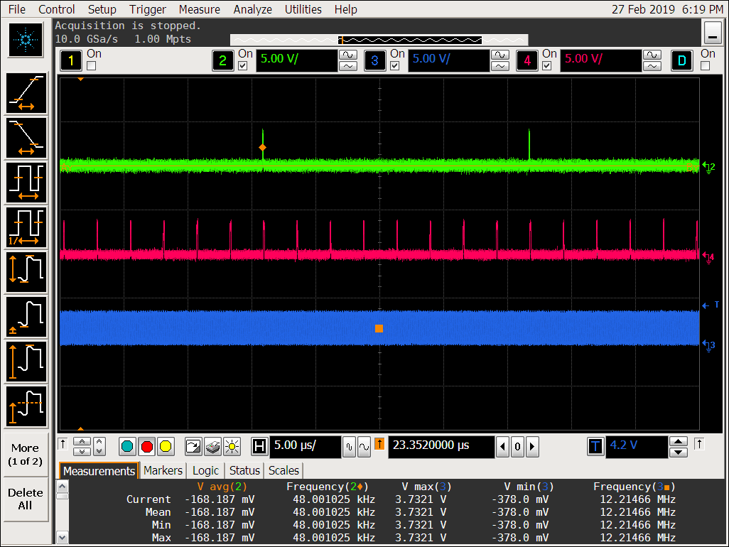
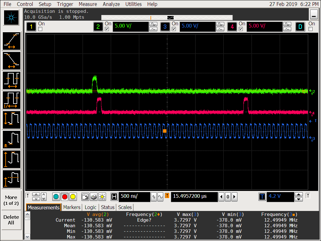
Here is what my input looks like. In these snapshots green is the LRCLK, pink is DIN, and blue is BCK. The example data here just sets the MSB of each channel/word high. Note that LRCLK is only high for one BCK period.
I appreciate the help!
-Peter


