This thread has been locked.

If you have a related question, please click the "Ask a related question" button in the top right corner. The newly created question will be automatically linked to this question.

PCM1795: I get only 5 bits?!

Part Number: PCM1795

Hi All,

I am trying to run the DAC in the application like attached. The very strange thing is that it seems to be 5 bits only, please see attached screenshots from the scope. For the purpose of this demo I played 1 kHz 0dB sine wave.
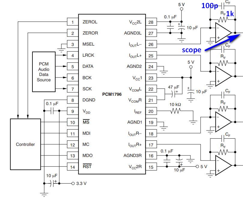
Schematic:

1 kHz sine wave

1 kHz sine wave zoomed in
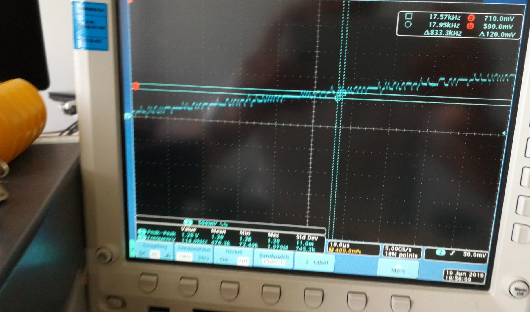
No playback

You can easily count the number of bits by looking at those pictures. Each of the LSBs corresponds to approx. 120 mV (after the I/V). How is that possible? What am I missing here?

Thanks very much for your support.

  • Hi Cezary,

    An important thing to note with this device is that it is current segment delta-sigma DAC.  These DACs feature current sources (about 70 of them), and switches very quickly between the number of them that are on and the number that is off.  They switch at the over sample rate of the device, which is then averaged by an internal, and external filters.  

    So take the example in the images you shared. You are providing samples to the device, commonly at 48ksps for audio.  The DAC is then over sampling at a higher rate, maybe 16× the sample rate.  This would give you switching frequency of about 768000Hz, which you are seeing I believe.

    You are also looking at the output of the TIA, so you do not really have much filtering at that point.  If you implement the 2nd order active filter on the next stage you will see that the switching from the DSM should be gone. 

    Thanks,

    Paul

  • Hi Paul,

    Thank you for your replay. I understand what you mean, however if you take standard audio CD data resolution, it would be 16 bits. I can then imagine using oversampling technique to get effectively more and more of the resolution, but still the base is 16 bits. In my case I can count precisely 32 steps, which gives 5 bits of resolution. Each step is then 4 mA / 32 = 125 uA or 125 mV after I/V conversion. Don't you think it is too coarse?

    Not mentioning that this sine wave is at 0dB. If I play -40dB, then I will not see any signal any more. Do you know what I mean?

    Regards,

    Cezary

  • Hi Cezary,

    Consider a PWM output.  Even though a PWM is essentially a 1 bit DAC (on and off), it can achieve higher resolution by averaging the output.  The DSM in the PCM1795 can be thought of like PWM, but instead of switching between totally on and totally off or full-scale and zero-scale, it has many different voltages it can switch between.  So just like how the 1 bit PWM could have higher resolution between its two output values, the PCM DSM can have higher resolution between all of its output values.  

    Now this is an over simplification, as the DSM implements a lot of features to remove segment errors, digital filtering, interpolation, etc.  

    If you are still skepical, I suggest you do a THD or dynamic range measurement with your filter implemented.  A true ~5 bit DAC would have an ideal Dynamic range and THD of about 32dB.  On a well implemented system, you can achieve a dynamic range measurement of 123dB, which represents an effective 20bit device.  Ideally the dynamic range would be be even greater, but we are limited by noise in the system.

    Thanks,

    Paul

  • Hi Paul,

    OK, I understand, thank you. Just wanted to make sure that what I see is normal and expected.

    Then the next question would be: how to effectively get rid off those unwanted frequencies? I am planning to used 128x oversampling, which means that I will get approx. 5.6 MHz switching frequency on the output 44.1k*128). Now, in the application section of the datasheet you recommend for I/V R1=820R and C1=2700p, which places the very first pole at f=72 kHz. Then the MFB low-pass filter realized by the difference amp again will add two poles at around f=70 kHz and this is all great, because in simulation I get something like -80dB at f=5.6 MHz. The trouble is that it results in phase shift of -52 degrees @ f=20 kHz. I was planning to place the poles at much higher frequency, to get minimum phase shift in 20 Hz - 20 kHz range, but then I will have more of the switching frequency. Is there anything wrong in my reasoning? How would you approach it?

    Regards,

    Cezary

  • Hi Cezary,

    There is always a compromise between reducing the out of band noise (switching noise and aliased signals >20kHz) and the phase shift.  There is generally very little content in standard audio at 20kHz, so many engineers will chose to have a lower frequency fC to reduce noise.

    Depending on the application, target a fC of about 75% the sample rate, as that is when the OoB noise starts to increase.  The higher the sample rate, the further this cutoff can be and therefore have less of a phase impact on the audible band.  So if possible, use a higher sample rate then you can have a nice high-order filter, while still preserving the phase in the audible band.

    Thanks,

    Paul