This thread has been locked.

If you have a related question, please click the "Ask a related question" button in the top right corner. The newly created question will be automatically linked to this question.

TAS5825-SW: Definition of tas5825m 0x40 register (DSP_PGM_MODE) and PPC dump settings

Part Number: TAS5825-SW
Other Parts Discussed in Thread: TAS5825M

Hi!

My customer is building up the EQ Tuning in the customer system by using the PPC3 tool to output the EQ Tuning as a dump file.
However, the expected tuning sound is not being output.So the customer is reviewing each of the Register settings.
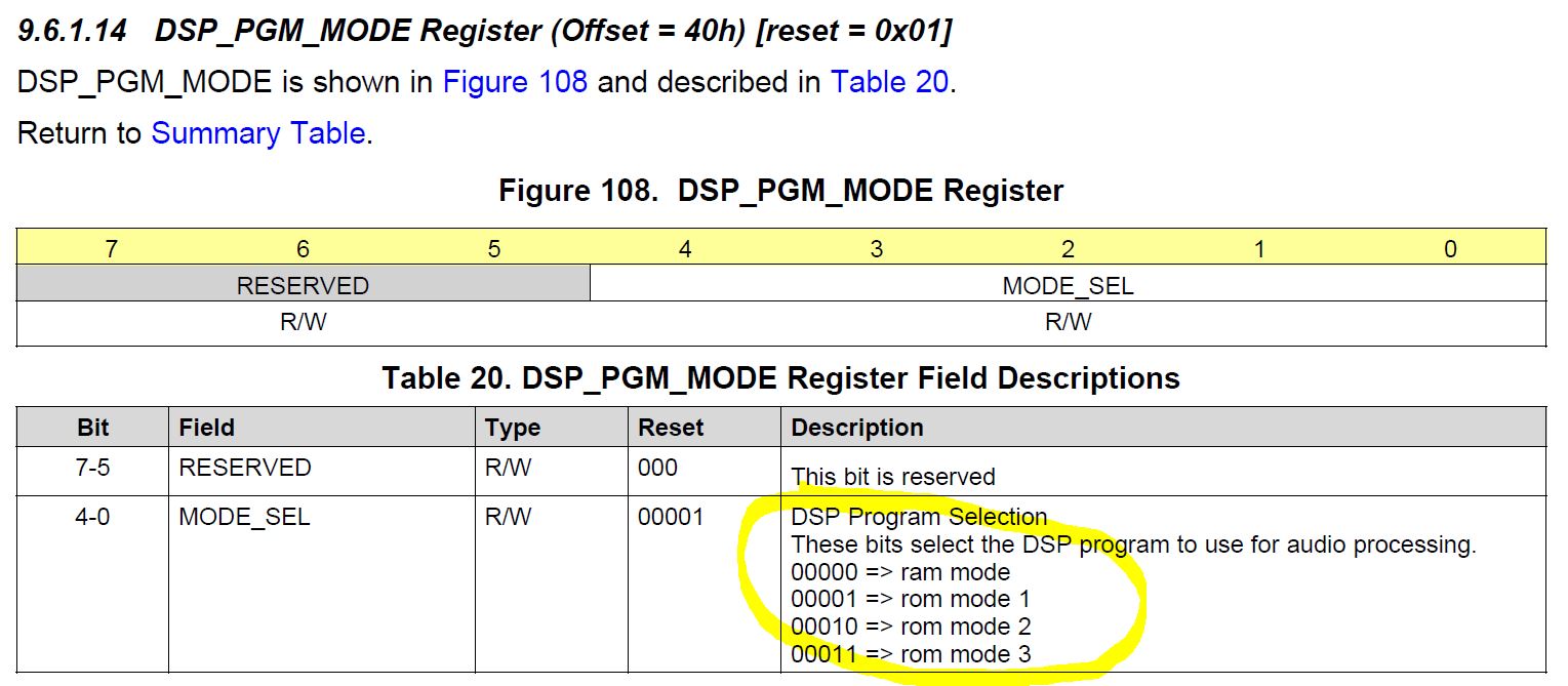
What is the difference between RAM mode and ROM mode in the figure below regarding the 0x40 register?


Can you tell me the difference between the modes below and the exact definition of the modes below? The Datasheet does not provide details.


1.RAM MODE
2.ROM MODE1
3.ROM MODE2
4.ROM MODE3

If 0x40 register is set to 0x00, the desired sound is outputted to 0x10, without the desired sound being output.

In addition, how do we set the test values in the EVM in a dump file so that we can build up our system?
There are five dump modes. Can you tell me the exact definition of the menu below?


1.default
2.current state
3.snapshot
4.current state -cold boot
5.custom

Please check it.

Thank you.

Best Regards.

From Anthony.

  • There are typos in the top, so correct them as follows.

    Setting 0x40 register to 0x00 does not produce the desired sound (low band cut off) and setting 0x40 register to 0x02 (ROM MODE2) is making the desired sound.

  • Hi Anthony,

    Some flows of TAS5825 are using Ram program, which need download program script. Others are Rom mode. All programs are fixed.

    TAS5825 only use 01 ROM and 00 RAM. So it's strange with your evaluation result. Does customer use EVM board or their system to produce this issue? If their system board, please re-check the start up sequence. It requires stable I2S before writing down I2C scrips.

    Regarding the dump mode, 'current state' is normally enough for general usage.

    Regards,

    Matthew

  • Hi! Matthew

    Thank you for your reply.

    I understood your advice well.

    On the customer side, we confirmed that it was not set according to the sequence you mentioned, and we are going to test the sequence by changing the sequence.

    Our current problem is that the Book 0xAA value of the TAS5825M will continue to change from the default value.

    Is it possible that the set register value can be changed when the required sequence is not followed?

    One thing I want to ask you again.

    You have to use RAM MODE, ROM MODE1,

    but we want to know exactly the difference between these modes.We will ask again for the exact definition of the mode below.

    1. RAM MODE

    2. ROM MODE1

    3.ROM MODE2

    4.ROM MODE3

    Thank you 

    Best regards

    From anthony.

  • Hi Anthony,

    Regarding 'Book0xAA register continue change to default value', could you help to clarify the detailed situation? The only possibility from my side is required start up sequence is not followed. TAS5825M DSP will reset RAM memory value to default value after I2S clock is provided. So it's suggested to modify set up sequence to check Book 0xAA registers again.

    What's more, only RAM and ROM1 are used currently. The purpose is to select different DSP flows, and PPC3 will handle this configuration.

    Regards,

    Matthew