This thread has been locked.

If you have a related question, please click the "Ask a related question" button in the top right corner. The newly created question will be automatically linked to this question.

TLV320DAC3100: Beep generator, MCLK waveform and Analog output waveform

Part Number: TLV320DAC3100

Hi all,

I'm trying to implementation beep sound with TLV320DAC3100. After setting several registers, I've already be able to generate beep sound successfully. However, I also want to check if or not our input MCLK waveform and analog output waveform is correct, because the analog output waveform does not look like what I expected (Maybe my expectation is wrong). What I expected is sine burst waveform.

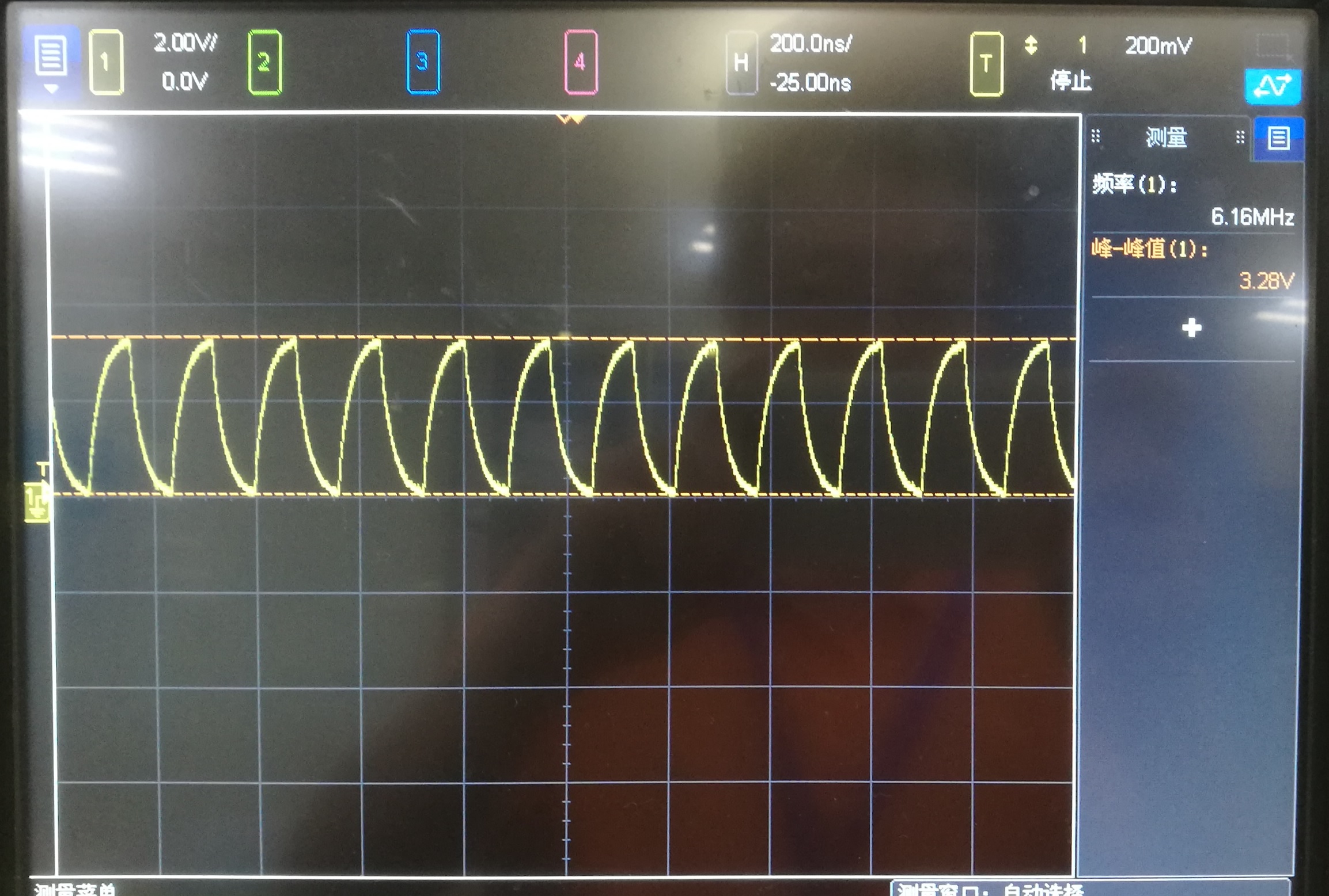
Here's my pic of input MCLK which is used as reference clock for PLL. It's not a square wave, but similar to sine wave. Frequency is about 6.16 MHz and amptitude is about 3.3V.

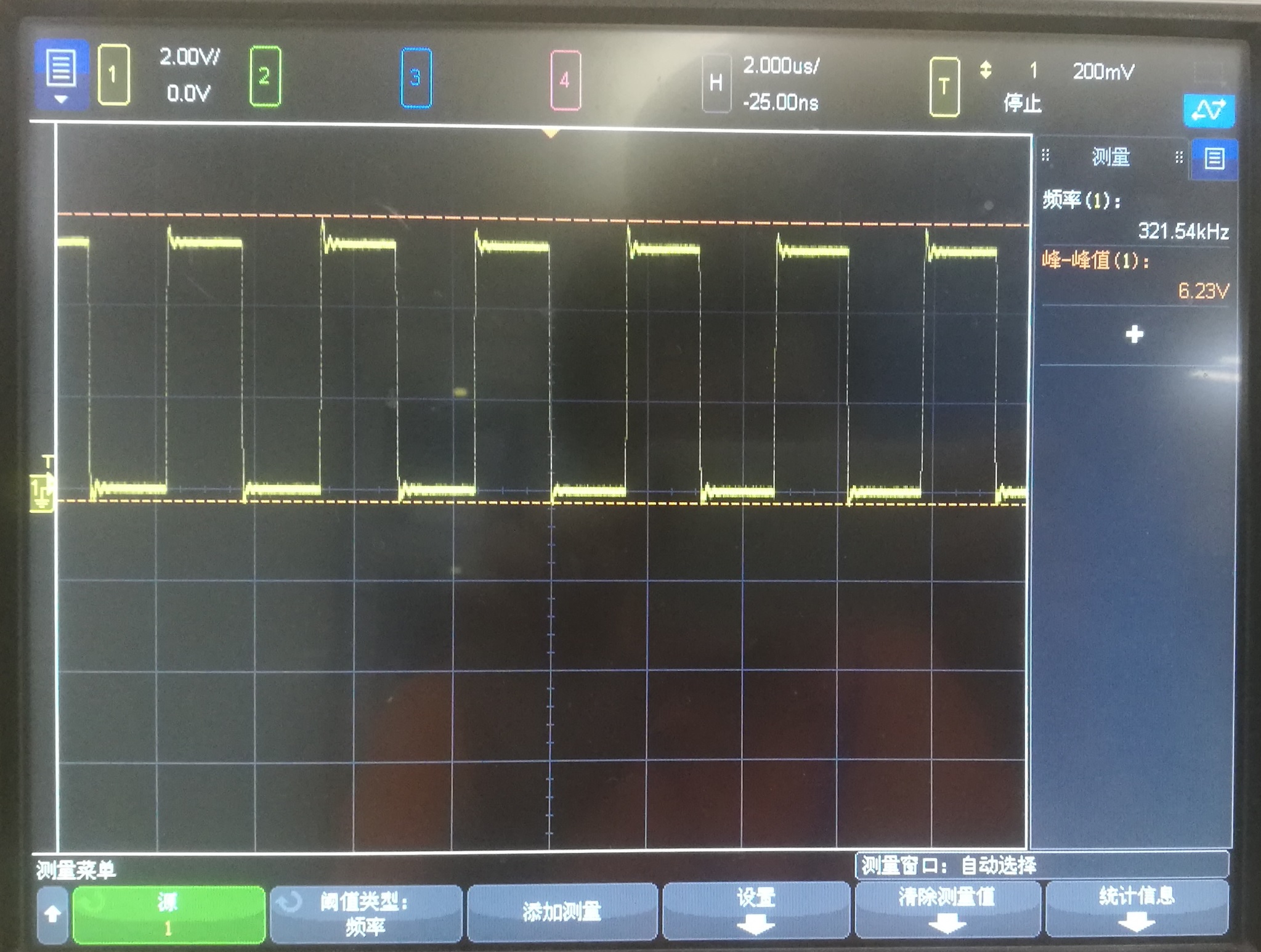
The second is analog output without beep sound. The frequency is about 320kHz, amptitude is more than 6V.

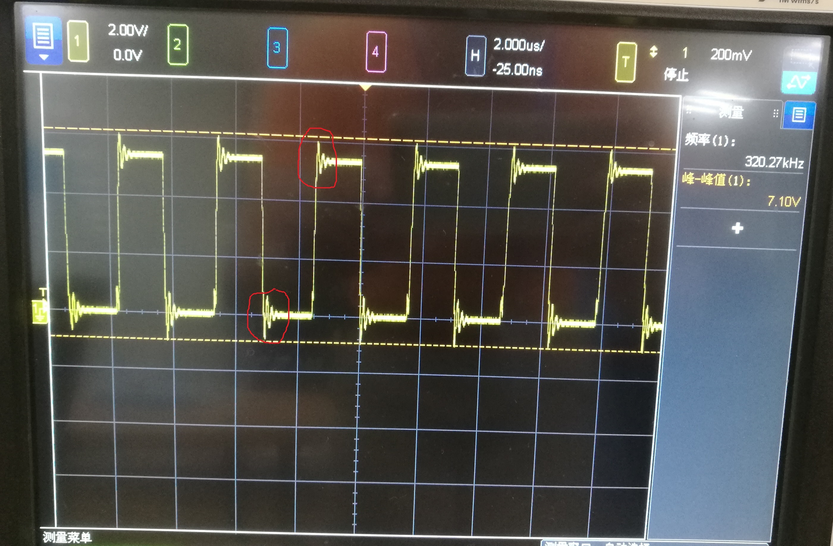
The last one is analog output waveform when beep sound exists. Compared with the second square wave, it has some peaks. The amptitudes of these peaks are controlled by beep volume gain (from -61dB to 2dB).

Why it is not a sine wave?

  • Hi,

    Welcome to E2E and thank you for your interest in our products!

    Could you provide your entire registers configuration? I will be helpful to understand this case correctly.

    Are you using a WCLK and BCLK too? At least a BCLK should be used or generated by the device in order to enable the processing blocks correctly. The processing blocks require of around 8 BCLK pulses to be initialized.

    Also, remember that the TLV320DAC3100 has Class-D output, so you would need to add a Class-D filter ( http://www.ti.com/lit/an/sloa107/sloa107.pdf ) to see the beep sinewave as you expect.

    Best regards,
    Luis Fernando Rodríguez S.

  • Here's my register configuration.

    page 0

    reg[4] = 0x3
    reg[5] = 0x92
    reg[6] = 0x7
    reg[7] = 0x0
    reg[8] = 0x0
    reg[11] = 0x82
    reg[12] = 0x87
    reg[13] = 0x0
    reg[14] = 0x80
    reg[25] = 0x5
    reg[26] = 0x81
    reg[27] = 0xc
    reg[28] = 0x0
    reg[29] = 0x1
    reg[30] = 0x82
    reg[60] = 0x19
    reg[63] = 0xdb

    page 1

    reg[32] = 0x86
    reg[35] = 0x44
    reg[38] = 0x80
    reg[42] = 0x1c

    page 0

    reg[73] = 0x7
    reg[74] = 0x53
    reg[75] = 0x0
    reg[76] = 0x18
    reg[77] = 0xf9
    reg[78] = 0x7d
    reg[79] = 0x8a
    reg[71] = 0x9b

    And I didn't use WCLK and BCLK. They are all grounded.

    BTW, today I used PWM output (6.144MHz) as MCLK to TLV32DAC3100. The analog output waveform is similar without real change.

  • Hi, Luis,

    My MCLK waveform to TLV320DAC3100 is not a sine wave, does it work for beep genenrator?

  • Hi,

    The MCLK waveform shouldn't be any problem if it respects the VIH and VIL parameters of the datasheet. However, you need to use or generate the BCLK pulses to/from the TLV320DAC3100. The processing blocks depend of some BCLK pulses to be fully initialized. Otherwise, you won't be able to use the beep generator feature.

    Best regards,
    Luis Fernando Rodríguez S.

  • Hi Luis,

    I double checked my code and found that I configured BCLK to be generated internally by using DAC_MOD_CLK as clock source. And now my input MCLK is square wave but its amptitude is more than 4V (my IOVDD is 3.3V), is it ok?

  • Hi, 

    In your previous post you mentioned that the BCLK pin is grounded. You should left it floating if you are generating it from the DAC_MOD_CLK source. Otherwise, there could be a short in the pin.

    In addition, regarding the MCLK amplitude, you should reduce this voltage level. The datasheet specifies that the digital pins cannot be higher than IOVDD + 0.3V. Using a higher voltage level may result in a permanent damage of the device.

    Best regards,
    Luis Fernando Rodríguez S.

  • Hi Luis,

    Thank you for your help!