This thread has been locked.

If you have a related question, please click the "Ask a related question" button in the top right corner. The newly created question will be automatically linked to this question.

TAS2563: How to sync two mother boards with total 4 pcs TAS2563 together?

Part Number: TAS2563
Other Parts Discussed in Thread: TAS2557, TAS2560

Dear team,

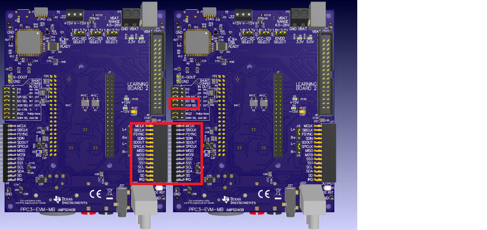
As title, do you know how to sync two mother boards with total 4 pcs TAS2563 together? Is it possible to sync delay and protection time? 

And I am interested in smart amplifier with low power output, such as the TAS2563, which has a mono channel. On the other hand, high power output, such as the TAS5825, have stereo channel. Is there any product reference design that can be shared with me? I am researching which products are right for my customer's project.

Thank you.

  • Hi, Kane,

    Regarding your question about the two mother boards synchronization, it would be necessary to ensure that each TAS2563 has different I2C address. Otherwise, there could be risk of data collision and there will be communication issues. Then, you would need to ensure that all the boards share the same I2S bus lines and all the I2S clocks are synchronized. If you can ensure it, you won't have synchronization delays.

    Regarding your question about the TAS2563, you may take a look at the TAS2560 or the TAS2557. Basically, these are mono versions of the TAS2563.

    I would recommend to post another E2E thread about the TAS5825 and its similar devices. This is a product from another Audio group. However, you may find some useful information about these products in this link below:

    http://www.ti.com/audio-ic/amplifiers/speaker-amplifiers/featured-products.html#Smartamps

    Let me know if you have additional questions or comments.

    Best regards,
    Luis Fernando Rodríguez S.

  • Hi Luis,

    Thanks for your reply.

    Based on your feedback, does it mean we don't need to connect "IC linking" to each TAS2563 if we share the same I2S bus? Should we keep the IC linking pin floating?

    Thanks,

    Bruce

  • Hi, Bruce,

    In stereo applications, the IC linking is used for cases where one channel must be protected against clipping. This feature is used to compensate the two channels according to the clipping protection. The IC linking pins can be left floated if not used.

    As example of a multichannel connection with two motherboards, you may take a look at the picture below. All the communication pins are connected between them. In the jumper J4 (which controls the TAS2563 routing to the MSP430), it is necessary to remove the I2C and I2S pins in one of the boards. In that way, the second board will use the clocks from the first motherboard.

    I hope to have been clear. Please let me know if you have additional questions or comments.

    Best regards,
    Luis Fernando Rodríguez S.

  • Hi Luis,

    Thanks for the illustration. We will try it and feedback if there's other quesition.

    Best regards,

    Bruce

  • Hi Luis,

    We're wondering could we use only one computer to tune 4 TAS2563 after connecting motherboards together?

    In PPC3, there's only "dual" and "mono" setting.

    For now, we use two computers to achieve the tuning for 4 amp.

    Thanks,

    Bruce

  • Hi, Bruce,

    PPC3 doesn't have enough capabilities to handle all 4 amps. However, you may tune the 4 amps manually trough the registers configuration. You would need to store all the registers data in the config files. Then, you would need to modify the I2C address of each register command for the amplifier that you would like to tune. These registers commands can be opened through PPC3 in order to configure the amps with their respective I2C address.

    Please let me know if this makes sense and if you have additional questions or comments.

    Best regards,
    Luis Fernando Rodríguez S.