This thread has been locked.

If you have a related question, please click the "Ask a related question" button in the top right corner. The newly created question will be automatically linked to this question.

PCM5141: Sequence for write Page 0x2C in PCM5141

Part Number: PCM5141
Other Parts Discussed in Thread: PCM5142

Hi Team,

   My customer want to use MCU to control PCM5141 registers and I want to know the correct sequence.

   1. I2C is OK, other registers can be read/write correctly.

   2. In the Interface of GDE, the address is as below. To page: 0x2C, Reg: 0x08, the I2C memory tool can read out 0xFF for Mono and 0x00 for Stereo.

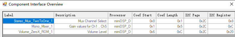
      3. But to MCU, I can't get correct access to the 0x08 in Page 0x2C, so what's the correct sequence?

      4. I can't find Register 0x8 in PCM514x's datasheet, can you also give me more info?

  • Hi Holly,

    I think the most important thing to understand here is that the miniDSP in the PCM5142 relies on a coefficient memory and an instruction memory.  Most of this device's features are only able to be implemented when the DSP is programmed to do so.  There are some blocks in the DSP that are static, but a custom process flow like this does not necessarily utilize them. 

    I think the confusion you are experiencing is because you are trying to access this register as though it is a pre-defined feature of the PCM.

    The component interface overview tool is only showing where the current process flow will store the coefficients when the code is generated.  This flow requires some coefficients and some instructions.  

    Take a look at the PPS file I saved in this zip and .cfg that it generates.

    base_main_Rate44.zip

    In order to implement this, your I2C master must do the following steps:

    1. Issue a standby request - the DSP memory is not accessible unless the device is in standby mode.

    2. Program the coefficient memory - this process flow requires 9 coefficients.

    3. Program the instruction memory - this process flow requires 59 instructions.

    4. Select program 31 (the custom Process Flow program) 

    5. Exit standby operation

    The device will now be operating in standby mode.

    The coefficients and instructions are generated by PurePath Studio after it compiles the DSP code.

    Thanks,

    Paul