This thread has been locked.

If you have a related question, please click the "Ask a related question" button in the top right corner. The newly created question will be automatically linked to this question.

TLV320AIC3104: Register setting to make path from MIC2R to HPROUT/HPLOUT

Part Number: TLV320AIC3104

Hello,

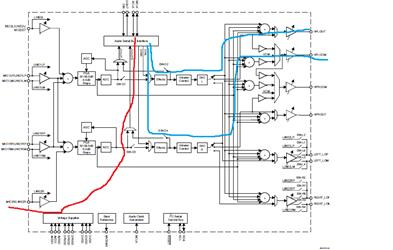
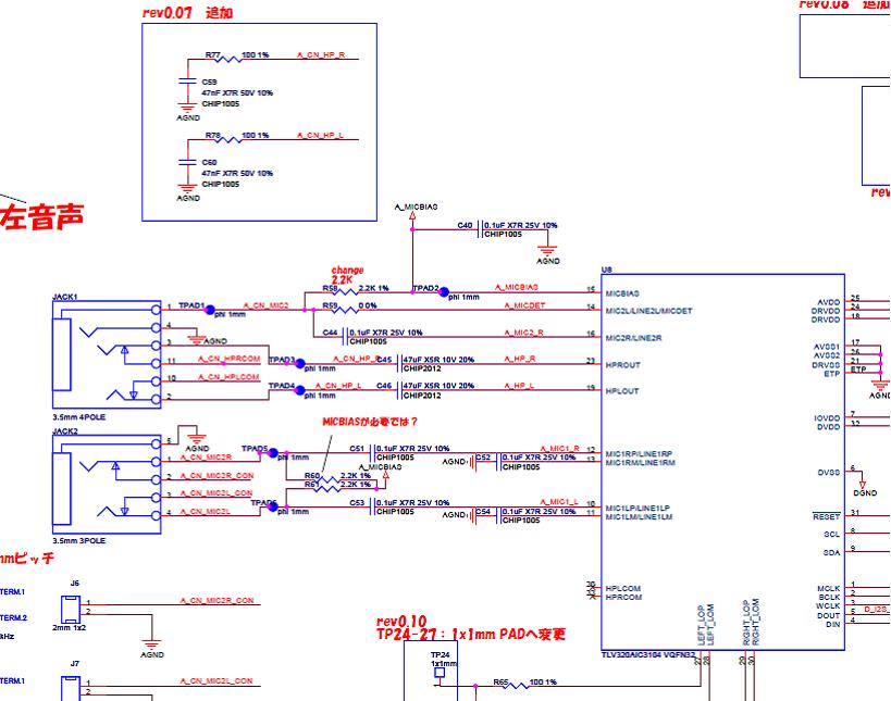
The customer wants to output sound from HPROUT/HPLOUT as same sound as MIC2R for debug purpose but they can't do this yet.

They would like TI to advise what register setting is mistaking.. Would you review the register setting? The path image is attached. Either red or blue line is ok for debug purpose.

The below is register dump information.

[  0] = (0x00)

[  1] = (0x00)

[  2] = (0x00)

[  3] = (0x10)

[  4] = (0x04)

[  5] = (0x00)

[  6] = (0x00)

[  7] = (0x0a)

[  8] = (0x20)

[  9] = (0x00)

[ 10] = (0x00)

[ 11] = (0x31)

[ 12] = (0x00)

[ 13] = (0x8b)

[ 14] = (0x80)

[ 15] = (0x00)

[ 16] = (0x00)

[ 17] = (0xf0)

[ 18] = (0xff)

[ 19] = (0x7f)

[ 20] = (0x78)

[ 21] = (0x78)

[ 22] = (0x7f)

[ 23] = (0x78)

[ 24] = (0x78)

[ 25] = (0x46)

[ 26] = (0x00)

[ 27] = (0xfe)

[ 28] = (0x00)

[ 29] = (0x00)

[ 30] = (0xfe)

[ 31] = (0x00)

[ 32] = (0x00)

[ 33] = (0x00)

[ 34] = (0x00)

[ 35] = (0x00)

[ 36] = (0xcc)

[ 37] = (0x20)

[ 38] = (0x06)

[ 39] = (0x00)

[ 40] = (0x02)

[ 41] = (0x00)

[ 42] = (0x00)

[ 43] = (0x00)

[ 44] = (0x00)

[ 45] = (0x00)

[ 46] = (0x80)

[ 47] = (0x00)

[ 48] = (0x00)

[ 49] = (0x00)

[ 50] = (0x00)

[ 51] = (0x0f)

[ 52] = (0x00)

[ 53] = (0x00)

[ 54] = (0x00)

[ 55] = (0x00)

[ 56] = (0x00)

[ 57] = (0x00)

[ 58] = (0x04)

[ 59] = (0x00)

[ 60] = (0x00)

[ 61] = (0x00)

[ 62] = (0x00)

[ 63] = (0x80)

[ 64] = (0x00)

[ 65] = (0x0f)

[ 66] = (0x00)

[ 67] = (0x00)

[ 68] = (0x00)

[ 69] = (0x00)

[ 70] = (0x00)

[ 71] = (0x00)

[ 72] = (0x06)

[ 73] = (0x00)

[ 74] = (0x00)

[ 75] = (0x00)

[ 76] = (0x00)

[ 77] = (0x00)

[ 78] = (0x00)

[ 79] = (0x00)

[ 80] = (0x00)

[ 81] = (0x00)

[ 82] = (0x00)

[ 83] = (0x00)

[ 84] = (0x00)

[ 85] = (0x00)

[ 86] = (0x00)

[ 87] = (0x00)

[ 88] = (0x00)

[ 89] = (0x00)

[ 90] = (0x00)

[ 91] = (0x00)

[ 92] = (0x00)

[ 93] = (0x00)

[ 94] = (0x06)

[ 95] = (0xc4)

[ 96] = (0xc4)

[ 97] = (0xc4)

[ 98] = (0x00)

[ 99] = (0x00)

[100] = (0x00)

[101] = (0x01)

[102] = (0x02)

[103] = (0x00)

[104] = (0x00)

[105] = (0x00)

[106] = (0x00)

[107] = (0x00)

[108] = (0x00)

[109] = (0x00)

[110] = (0x00)

[111] = (0x00)

[112] = (0x00)

[113] = (0x00)

[114] = (0x00)

[115] = (0x00)

[116] = (0x00)

[117] = (0x00)

[118] = (0x00)

[119] = (0x00)

[120] = (0x00)

[121] = (0x00)

[122] = (0x00)

[123] = (0x00)

[124] = (0x00)

[125] = (0x00)

[126] = (0x00)

Best regards,

Toshihiro Watanabe

  • Hello Toshihiro,

    Is the customer just using the MIC2R input for debug purposes? If so, here are my recommended setting. I will be using the red path:

    [17] = (0xFF) //Does not route MIC2R to LADC

    [49] = (0x80) //Routs PGA_R to HPLOUT

    [63] = (0x80) //Routs PGA_R to HPROUT

    These should be the only registers the customer should need to make. Everything else looks good. 

    Regards,

    Aaron

  • Hello Aaron-san,

    The customer tried the register setting however HPLOUT/HPROUT didn't work properly.

    They changed the path as attached. They can get mic waveform from MPU by red line.

    They write waveform data by blue line however  HPLOUT/HPROUT didn't work properly.

    Would you advise us what is the issue not to work   HPLOUT/HPROUT ?

    The below is the register setting. 

    [  0] = (0x00)

    [  1] = (0x00)

    [  2] = (0x00)

    [  3] = (0x10)

    [  4] = (0x04)

    [  5] = (0x00)

    [  6] = (0x00)

    [  7] = (0x0a)

    [  8] = (0x20)

    [  9] = (0x00)

    [ 10] = (0x00)

    [ 11] = (0x31)

    [ 12] = (0x00)

    [ 13] = (0x8b)

    [ 14] = (0x80)

    [ 15] = (0x00)

    [ 16] = (0x00)

    [ 17] = (0xff)

    [ 18] = (0xff)

    [ 19] = (0x07)

    [ 20] = (0x78)

    [ 21] = (0x78)

    [ 22] = (0x07)

    [ 23] = (0x78)

    [ 24] = (0x78)

    [ 25] = (0x46)

    [ 26] = (0x00)

    [ 27] = (0xfe)

    [ 28] = (0x00)

    [ 29] = (0x00)

    [ 30] = (0xfe)

    [ 31] = (0x00)

    [ 32] = (0x00)

    [ 33] = (0x00)

    [ 34] = (0x00)

    [ 35] = (0x00)

    [ 36] = (0xcc)

    [ 37] = (0xe0)

    [ 38] = (0x06)

    [ 39] = (0x00)

    [ 40] = (0x02)

    [ 41] = (0x01)

    [ 42] = (0x00)

    [ 43] = (0x00)

    [ 44] = (0x00)

    [ 45] = (0x00)

    [ 46] = (0x00)

    [ 47] = (0x80)

    [ 48] = (0x00)

    [ 49] = (0x00)

    [ 50] = (0x00)

    [ 51] = (0x0f)

    [ 52] = (0x00)

    [ 53] = (0x00)

    [ 54] = (0x00)

    [ 55] = (0x00)

    [ 56] = (0x00)

    [ 57] = (0x00)

    [ 58] = (0x04)

    [ 59] = (0x00)

    [ 60] = (0x00)

    [ 61] = (0x00)

    [ 62] = (0x00)

    [ 63] = (0x00)

    [ 64] = (0x80)

    [ 65] = (0x0f)

    [ 66] = (0x00)

    [ 67] = (0x00)

    [ 68] = (0x00)

    [ 69] = (0x00)

    [ 70] = (0x00)

    [ 71] = (0x00)

    [ 72] = (0x06)

    [ 73] = (0x00)

    [ 74] = (0x00)

    [ 75] = (0x00)

    [ 76] = (0x00)

    [ 77] = (0x00)

    [ 78] = (0x00)

    [ 79] = (0x00)

    [ 80] = (0x00)

    [ 81] = (0x00)

    [ 82] = (0x00)

    [ 83] = (0x00)

    [ 84] = (0x00)

    [ 85] = (0x00)

    [ 86] = (0x00)

    [ 87] = (0x00)

    [ 88] = (0x00)

    [ 89] = (0x00)

    [ 90] = (0x00)

    [ 91] = (0x00)

    [ 92] = (0x00)

    [ 93] = (0x00)

    [ 94] = (0xc6)

    [ 95] = (0xc4)

    [ 96] = (0xc4)

    [ 97] = (0xc4)

    [ 98] = (0x00)

    [ 99] = (0x00)

    [100] = (0x00)

    [101] = (0x01)

    [102] = (0x02)

    [103] = (0x00)

    [104] = (0x00)

    [105] = (0x00)

    [106] = (0x00)

    [107] = (0x00)

    [108] = (0x00)

    [109] = (0x00)

    [110] = (0x00)

    [111] = (0x00)

    [112] = (0x00)

    [113] = (0x00)

    [114] = (0x00)

    [115] = (0x00)

    [116] = (0x00)

    [117] = (0x00)

    [118] = (0x00)

    [119] = (0x00)

    [120] = (0x00)

    [121] = (0x00)

    [122] = (0x00)

    [123] = (0x00)

    [124] = (0x00)

    [125] = (0x00)

    [126] = (0x00)

    Best regards,

    Toshihiro Watanabe

  • Hello Toshihiro-san,

    The register settings look like everything is getting configured correctly. Let me run the configuration on an EVM here in the lab and I will get back to you as soon as possible. 

    In the mean time, can you confirm that the codec is getting the correct clock signals?

    Regards,

    Aaron

  • Hello Toshihiro-san,

    I tested the register configuration you provided and I was able to get an output on HPLOUT. I noticed that you followed the MIC2R path in the image you provided but have this path not connected to an ADC. Use register 18 to connect MIC2R to RADC.

    I would still suggest using the PGA bypass path as it provides a cleaner signal. Both the ADC and DAC will introduce noise and the PGA bypass will avoid this. It looks like i made an error above when providing the settings for PGA bypass. The updated PGA bypass settings are updated below

    [17] = (0xFF) //Does not route MIC2R to LADC

    [18] = (0xF0) //Routes MIC2R to FADC

    [19] = (0x78) //Does not route MIC1LP to LADC

    [22] = (0x78) //Does not route MIC1RP to RADC

    [49] = (0x80) //Routs PGA_R to HPLOUT

    [63] = (0x80) //Routs PGA_R to HPROUT

    Regards,
    Aaron

  • Hello Aaron-san,

    The customer tried the register setting however they couldn't see output from HPROUT/HPLOUT.

    Could you share us the all register information you tried on the EVM?

    The customer want to try I2S -> DAC -> HPROUT/HPLOUT path as attached.

    Could you advise us how to configure the register setting in this condition?

    Clock will be ok because they can capture mic input throuth I2S. They can double check the waveform.

    Best regards,

    Toshihiro Watanabe

  • Hello Toshihiro-san,

    Here are the following register settings I used in the following format:

    w - write, 0x30 GUI Address, 0xXX - Register, 0xXX - Value

    #page select 0
    w 30 00 00
    #software reset
    w 30 01 80
    #LData to LDAC, RData to RDAC
    w 30 07 0A
    #Tristate
    w 30 08 20
    #Headset detection enabled
    w 30 0D 8B
    #Headset detection
    w 30 0E 80
    #LPGA not muted
    w 30 0F 00
    #RPGA not muted
    w 30 10 00
    #MIC2R to RADC
    w 30 12 F0
    #LINE1LP connected to LADC, LADC powered on
    w 30 13 7C
    #LINE1RP connected to RADC, RDAC powered on
    w 30 16 7C
    #MICBIAS set to 2V. Not sure why 6 is written in last bits
    w 30 19 46
    #LDAC,RDAC powered on. HPLCOM ind. SE
    w 30 25 E0
    #Short Circuit
    w 30 26 06
    #VCM 1.35V
    w 30 28 02
    #LDAC sel L1, RDAC sel R1. LDAC vol follows RDAC vol
    w 30 29 01
    #LDAC unmute
    w 30 2B 00
    #RDAC unmute
    w 30 2C 00
    #L1 to HPLOUT
    w 30 2F 80
    #HPLOUT unmute, fully powered up
    w 30 33 0F
    #DAC R1 to HPROUT
    w 30 40 80
    #HPROUT not muted, fully powered up
    w 30 41 0F
    #CODEC CLK uses CLKDIV_Out
    w 30 65 01
    #CLKDIV_IN uses MCLK
    w 30 66 02

    With the above register settings, I am able to feed analog in through MIC2R to DOUT and able to receive I2S at DIN and see output on HPLOUT and HPROUT. Please let me know if progress has been made.

    Regards,

    Aaron

  • Hello Aaron-san,

    We found Register 95 short circuit detection. If short circuit detection function is disable, we could see waveform from HPROUT/HPLOUT.

    Would you advise us why short circuit detection worked? Please let us know what information is needed to find this issue?

    Best regards,

    Toshihiro Watanabe

  • Hello Toshihiro-san,

    Since the customer is writing 0x06 to short circuit register, they are setting the bit that controls HPOUT power when there is a short circuit. If there is a short detected, the HPOUTs will power down. Is the customer seeing a short at the HPOUTs?

    Regards,

    Aaron

  • Hello Aaron-san,

    The customer didn't see a short at the HPOUTs at the moment. They will continue to investigate this but would you review the schematic around HPOUT just in case?

    Best regards,

    Toshihiro Watanabe

  • Hello Toshihiro,

    I do not see anything alarming in the schematic. Let me discuss this with a colleague and I will get back to you.

    Regards,

    Aaron

  • Hello Toshihiro,

    Apologies for the delayed response. One thing to trigger the short detect is having the load resistance lower than 16ohms (Minimum load resistance for headphone outs described in the data sheet).

    Regards,

    Aaron