1) At present, our code is as follows, but the sound can be collected when playing the song, but it is not the song sound at all;Can you help me review the code? What's wrong?
//I2S
//TLV320ADC5140 is as a Slave mode;
//FSYNC = 16 kHz ( Sample Rate), BCLK = 2.56MHz (BCLK/FSYNC = 16)
//ch2 ; Analog single-ended input
res=TLV320_Write_Reg(0,0); //Bank0
if(res)return 1;
delay_ms(2);
res=TLV320_Write_Reg(0x01,0X01);//
delay_ms(2);
res=TLV320_Write_Reg(0x02,0X81);//Sleep, AREG
delay_ms(2);
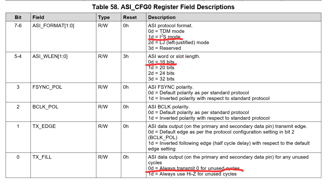
res=TLV320_Write_Reg(0x07,0X40);//ASI_CFG0
delay_ms(2);
res=TLV320_Write_Reg(0x08,0X20);//ASI_CFG1
delay_ms(2);
res=TLV320_Write_Reg(0x0B,0X01);//ASI_CFG1
delay_ms(2);
res=TLV320_Write_Reg(0x0C,0X00);//ASI_CFG1
delay_ms(2);
res=TLV320_Write_Reg(0x13,0X00);//MST_CFG0
delay_ms(2);
res=TLV320_Write_Reg(0x16,0X80);//CLK_SRC MCLK
delay_ms(2);
//chann2
res=TLV320_Write_Reg(0x41,0X21);//
delay_ms(2);
res=TLV320_Write_Reg(0x42,0XA8);//
delay_ms(2);
res=TLV320_Write_Reg(0x43,0X99);//
delay_ms(2);
res=TLV320_Write_Reg(0x44,0X00);//
delay_ms(2);
res=TLV320_Write_Reg(0x45,0X00);//
delay_ms(2);
res=TLV320_Write_Reg(0x6C,0X48);//
delay_ms(2);
res=TLV320_Write_Reg(0x70,0X00);//
delay_ms(2);
res=TLV320_Write_Reg(0x73,0X40);//IN_CH_EN
delay_ms(2);
res=TLV320_Write_Reg(0x74,0X40);//ASI_OUT_CH_EN
delay_ms(2);
res=TLV320_Write_Reg(0x75,0XE0);//PWR_CFG
delay_ms(2);
res=TLV320_Write_Reg(0x76,0X40);//
delay_ms(2);
res=TLV320_Write_Reg(0x77,0XE0);//
delay_ms(2);
//I2S
//TLV320ADC5140 is as a Slave mode;
//FSYNC = 16 kHz ( Sample Rate), BCLK = 2.56MHz (BCLK/FSYNC = 16)
//ch2 ; Analog single-ended input
res=TLV320_Write_Reg(0,0); //Bank0
if(res)return 1;
delay_ms(2);
res=TLV320_Write_Reg(0x01,0X01);//
delay_ms(2);
res=TLV320_Write_Reg(0x02,0X81);//Sleep, AREG
delay_ms(2);
res=TLV320_Write_Reg(0x07,0X40);//ASI_CFG0
delay_ms(2);
res=TLV320_Write_Reg(0x08,0X20);//ASI_CFG1
delay_ms(2);
res=TLV320_Write_Reg(0x0B,0X01);//ASI_CFG1
delay_ms(2);
res=TLV320_Write_Reg(0x0C,0X00);//ASI_CFG1
delay_ms(2);
res=TLV320_Write_Reg(0x13,0X00);//MST_CFG0
delay_ms(2);
res=TLV320_Write_Reg(0x16,0X80);//CLK_SRC MCLK
delay_ms(2);
//chann2
res=TLV320_Write_Reg(0x41,0X21);//
delay_ms(2);
res=TLV320_Write_Reg(0x42,0XA8);//
delay_ms(2);
res=TLV320_Write_Reg(0x43,0X99);//
delay_ms(2);
res=TLV320_Write_Reg(0x44,0X00);//
delay_ms(2);
res=TLV320_Write_Reg(0x45,0X00);//
delay_ms(2);
res=TLV320_Write_Reg(0x6C,0X48);//
delay_ms(2);
res=TLV320_Write_Reg(0x70,0X00);//
delay_ms(2);
res=TLV320_Write_Reg(0x73,0X40);//IN_CH_EN
delay_ms(2);
res=TLV320_Write_Reg(0x74,0X40);//ASI_OUT_CH_EN
delay_ms(2);
res=TLV320_Write_Reg(0x75,0XE0);//PWR_CFG
delay_ms(2);
res=TLV320_Write_Reg(0x76,0X40);//
delay_ms(2);
res=TLV320_Write_Reg(0x77,0XE0);//
delay_ms(2);
2)The device integrates programmable channel gain and digital volume control System, programmable microphone bias voltage, PLL, programmable high Pass filter (HPF), biquadratic filter, low delay filter mode,But we check the datasheet, which describes that the registers are all in page 0x00 to 0x04; we can only configure page 0x00, Will page 0x01 to 0x 04 not be provided to our users? How do we configure these Register parameters?
3)we check the “ Using the Automatic Gain Controller (AGC) in the TLV320ADCx140 ”。It is refer to page 0x06 to 0x07;Will page 0x06 to 0x 07 not be provided to our users?
4)if these page 0x01 to 0x 07 is not be provided to our users ,Can the parameters of the sound quality filter be set automatically? Where can I set it up?