This thread has been locked.

If you have a related question, please click the "Ask a related question" button in the top right corner. The newly created question will be automatically linked to this question.

RC4580: Why 4580 self-oscillation on Automobile Test Equipment of Simulated Solar Radiation

Part Number: RC4580
Other Parts Discussed in Thread: RC4558

Hi:

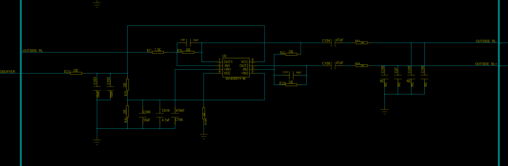
I use RC4580 amplify audio signal in my circuit.  Attached is the schematic. The RC4558 self-oscillation on Automobile Test Equipment of Simulated Solar Radiation. Net OUTSIDE RL connect to power amplifier. First I thought input of power amplifier have capacitor connect to GND.  I simulate my schematic using spice and input capacitor of power amplifier will cause oscillation when it greater than 3nF.  But manufacturer told me that they have putted the capacitor off. So I do not know why RC4558 self-oscillation ? Can you give me some suggestion? Thanks.

  • Hi, 

    Welcome to E2E and thank you for your interest in our products!

    Our team will take a look at this and will answer as soon as possible.

    Thank you.

    Best regards,
    Luis Fernando Rodríguez S.

  • Hi,

    Have you tried by removing C104 and C108? These might be capacitively loading the amplifier.
    In addition, since the output is differential these coupling capacitors should not be needed.

    If you need to keep these capacitors, perhaps you can add series resistors to isolate the capacitance from the outputs of the amplifier.

    Best regards,
    -Ivan Salazar
    Applications Engineer  - Low Power Audio & Actuators

  • Thank you for your answer.

    I have not remove C104 and C108,

    How can I  calculate value of capacitively loading include C104&C108 ? I think these will decease capacitance loading becasuse they series with input capacitor of  power amplifier,right ?

    The RC4580 work ok if add series resistors (R41,R48 change to 100R) 

    I want to know why 4580 self-oscillation under Test Equipment. 

    By the way, 4580 work ok under normal temperature condition.

  • Hi,

    Is my understanding correct that you have a working solution now?

    Perhaps the traces that connect the output of the amplifier to the speaker, in addition with output coupling capacitors (47uF) and the test equipment is capacitively loading the amplifier. By adding 100R you're isolating the amplifier from the output traces and test equipment capacitance and thus improving stability.

    Best regards,
    -Ivan Salazar
    Applications Engineer  - Low Power Audio & Actuators

  • Yes, I can solve this problem adding 100R

    Thank you for your suggetion. I measured wire between op and power amp . The distributed capacitive is 2nF. The length of wire is 7 meter. So may be that's why distributed capacitive is so large.

    By the way, can you tell me the output resistance of RC4580 (Ro) ? I have not found it in datasheet ,Thanks again. 

  • Unfortunately since there is not a value in the data sheet, this is most likely not available.

    There is HSpice model available, perhaps you can run simulations on the concerns you have about Ro.

    Best regards,
    -Ivan Salazar
    Applications Engineer  - Low Power Audio & Actuators