This thread has been locked.

If you have a related question, please click the "Ask a related question" button in the top right corner. The newly created question will be automatically linked to this question.

SRC4392: Can the SRC do 16-bit to 24-bit conversion?

Part Number: SRC4392
Other Parts Discussed in Thread: PCM5142

Hi,

I have an almost-working prototype using an SRC4392 feeding a PCM5142, but I have one last problem: 16-bit data files won't play.

I'm feeding I2S audio into Port B set up as a slave, with the Port B data format set to 24-bit I2S.

Data from Port B goes through the SRC and is sent out Port A to the PCM 5142.

Port A is set up as a master and sends 24-bit I2S at 192kHz. 

Port A and the SRC are driven by a 24.576MHz MCLK .

The PCM5142 receives 3-wire I2S (no SCK)  so it is in slave mode.

Playing 24-bit and 32-bit files at 44.1kHz, 48kHz, 96kHz or 192kHz works fine. 16-bit files at 44.1kHz or 48kHz result in silence.

The RDY pin is pulled low for all files (inc. 16-bit) so it appears that Port B is receiving and the SRC is locking on to the clock for 16-bit files, but no output from Port A.

The 0x32 and 0x33 registers show the correct ratio for all of the files, including 16-bit.

Is this a supported use case? In other words, should the SRC4392 be able to output 24-bit 192kHz I2S data from 16-bit I2S input data? The I2S spec says that the received should complete or truncate incoming data to match its internal work length.

Thanks in advance,

Peter

  • Hi Peter!

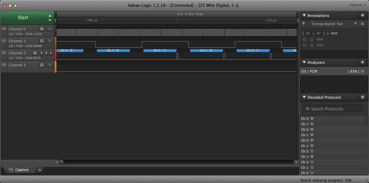
    Welcome to our e2e forum!  Do you by chance have screen shots of your I2S data stream?  I am curious as to how you are sending the 16-bit data to Port B.

  • Tom,

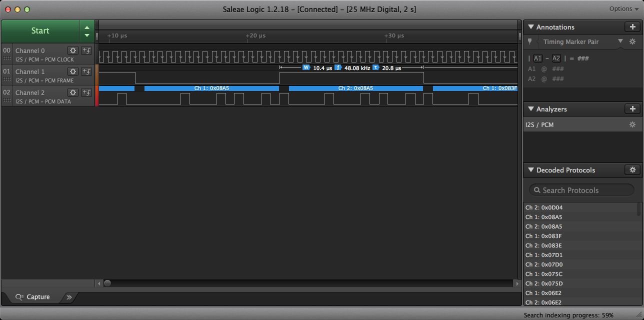
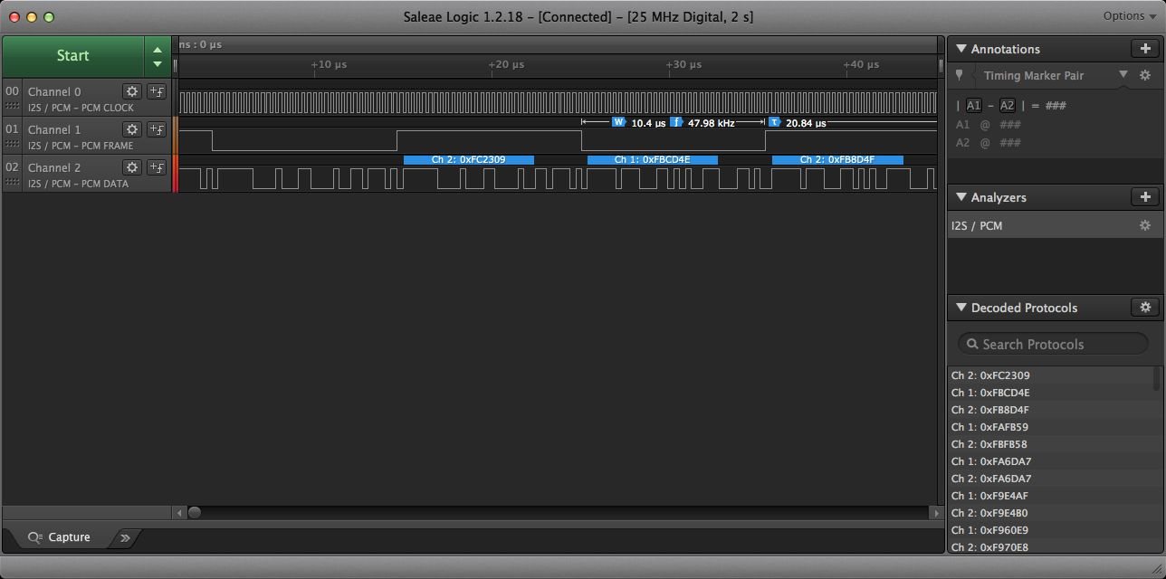
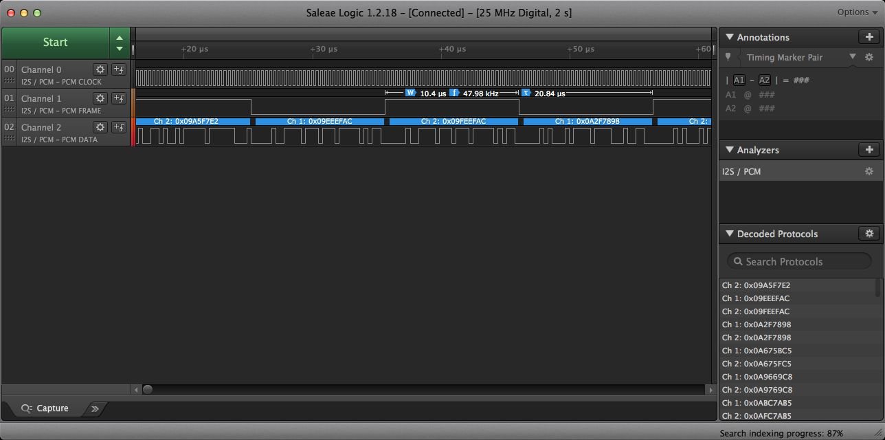
    Thanks for the welcome and the response. I have a couple screenshots from my logic analyzer. They are 16,24 and 32-bit samples, all at 48kHz.  IIRC I was using a 440Hz sine tone file.  Hopefully these are what you need.

    Peter

  • Hi Peter,

    I don't believe this is a supported use case. If a port is set to I2S, it is expecting 24 bits of data. This can be truncated using the integrated dithering function described in the datasheet below:

    The SRC provides a simple word length reduction mechanism for reducing 24-bit audio data to 20-, 18-, or 16-bit output word lengths. Word length reduction is performed utilizing triangular probability density function (or TPDF) dither. The OWL0 and OWL1 bits in control register 0x2F are utilized to set the SRC output word length. One note concerning the SRC output word length setting: when using the SRC output as the data source for either the Port A or Port B serial data outputs, and the audio serial port data format is set to Right-Justified, the word length set for the audio serial port format must match the word length set for the SRC output data.

    To me this, along with the Port control registers, implies that if you have less than 24-bits of data, you should use right justified mode. And in right justified mode, the output word length must match the input word length.

    Best,

    Zak

  • Zak,

    I suspect you're right in that it is a case that the SRC4392 doesn't support, but it is weird since it should work.  That's why I2S is MSB-first.  The Philips I2S spec says:

    "Serial data is transmitted in two’s complement with the MSB first. The MSB is transmitted first because the transmitter and receiver may have different word lengths. It isn’t necessary for the transmitter to know how many bits the receiver can handle, nor does the receiver need to know how many bits are being transmitted.

    When the system word length is greater than the transmitter word length, the word is truncated (least significant data bits are set to ‘0’) for data transmission. If the receiver is sent more bits than its word length, the bits after the LSB are ignored. On the other hand, if the receiver is sent fewer bits than its word length, the missing bits are set to zero internally. And so, the MSB has a fixed position, whereas the position of the LSB depends on the word length. The transmitter always sends the MSB of the next word one clock period after the WS changes


    If it was necessary to specify the input word length for I2S, then it is strange that the SRC4392 doesn't have an option for 16-bit I2S, which represents far more of the available data than any other format. And weird that the SRC4392 works fine with 32-bit I2S sent to a port configured for 24-bit.  I should take a look at the data being sent out of Port A (set to 24-bit) when I feed 32-bit into Port B.

    It is also odd that the PCM5142 happily changes from 16,24, and 32-bit I2S without any further info when fed directly.

    If the SRC4392 just doesn't work according to the I2S spec I can work around that by upsampling to 24-bit upstream, or switch to an AKM part :-) 

    Thanks,

    Peter

  • Peter Tait said:

    Tom,

    Thanks for the welcome and the response. I have a couple screenshots from my logic analyzer. They are 16,24 and 32-bit samples, all at 48kHz.  IIRC I was using a 440Hz sine tone file.  Hopefully these are what you need.

    Peter

    Peter,

    So for your port A master output, do you see LRCLK and the data output bit toggling when Port B feeds 16-bit samples?

    As a workaround, can the master on Port B force a 24-bit output with 16-bit samples (stuff the LSbs with zero)?

    I've only used the SRC4392 in the mode where each frame is 32 bits per sample.

  • Andy,

    I will take a look at the Port A output and be back.  Unfortunately I didn't allow for any test points between the 4392 and the 5142 so it's tricky to get the logic probes in there :-) I may also try to simulate this on a PCM5142EVM I have here.

    The workaround of having the master just send everything as 24-bit is working fine for now.

    Thanks,

    Peter

  • Peter Tait said:

    Andy,

    I will take a look at the Port A output and be back.  Unfortunately I didn't allow for any test points between the 4392 and the 5142 so it's tricky to get the logic probes in there :-) I may also try to simulate this on a PCM5142EVM I have here.

    Come on, surely you can get a couple of 'scope probes on the pins. It's just a regular QFP, not tiny at all :)

  • Hi Peter!

    That is basically where I was headed - left shift the 16-bit data and run it as 24-bits to the SRC and see what happens.

    Andy - the tough part is having that third arm/hand to be able to stop the scope trigger while holding scope probes against LRCLK, BCLK and Data.  Having a buddy in the lab might violate social distancing rules :).

  • Tom Hendrick said:

    Andy - the tough part is having that third arm/hand to be able to stop the scope trigger while holding scope probes against LRCLK, BCLK and Data.  Having a buddy in the lab might violate social distancing rules :).

    Ahhhhh, you don't need fancy triggering. Just use auto edge triggering, with the LRCLK input as the source. Let it run. You'll either see the outputs wiggle or not!
    Also, a good skill to develop is the art of tack-soldering a short (1 or 2 cm) lead of 30 AWG kynar-coated wire (wire-wrap wire) to the top of the pins. You can carefully put a 'scope probe grab hook on the other end of the wire. (Maybe use kapton tape to hold the body of the probe down.) Or use those grabby guys that come with the logic analyzer pod to hook onto those leads, and use the little black jumper guys with the 0.025" pin on one end and socket on the other to extend from the grabby guy to the 'scope probe.
    You don't really care about Howard Johnson-quality signal integrity with your measurements. You just want to see if the outputs are toggling!
  • Andy,

    Thanks for the 30 AWG wire wrap suggestion. I was thinking about tagging some test points on the chip, but didn't think I had anything fine enough.  But I'm pretty sure there's some old wrap wire around here somewhere...

    Peter

  • Update:

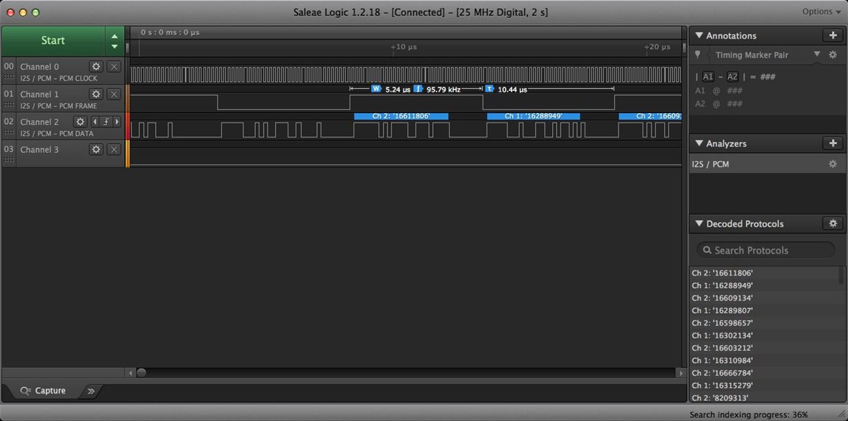
    I managed to attach a couple of leads to the inputs of the PCM5142, and took a look at the data when sending different bit lengths into the SRC4392.  24-bit and 32-bit inputs at 44.1, 48, 96 and 192kHz all resulted in the same 24-bit 96kHz I2S data flowing from Port A to the PCM5142.  I slowed the transfer down to 96kHz from 192kHz so it was a little easier for my analyzer.

    Sending 16-bit data into the SRC4392 resulted in CLOCK and FRAME at the right rate, but almost nothing on the DATA line.  But there were random looking pieces of data.

    Here are the 96kHz DAC inputs when the SRC is receiving 192kHz 32-bit and 48kHz 16-bit inputs:

    Any ideas?

    Peter

  • Hi Peter,

    This is with the original 16-bit data, like the Saleae plot that you sent over last Wednesday correct?  What do the results look like if you left shift and send it as a 32-bit word?

  • Tom,

    Do you mean "left shift and send a 32-bit word" from the SRC4392 to the PCM5142 (ie. change the SRC and Port A output selections) or "left shift and send a 32-bit word" from the source to the SRC4392?

    The latter case is what I am doing now - I configured the source to "resample" the output to 32-bits at it's original sample rate - and that works fine. I used 32-bit since the software on the source seems to want to output some files as 32-bit and I didn't want it to force it to downsample back to 24-bit.  Doesn't seem like a big load since it's just packing zeros in there.

    If you mean the former case, then my options for the Port A output in Register 03 are:

     24-Bit Left-Justified (Default for the SRC4392)

     24-Bit Philips I2S (my current selection)

    16-Bit Right-Justified

    18-Bit Right-Justified

     20-Bit Right-Justified

     24-Bit Right-Justified

    For the right-justified options I also need to change the SRC output in Register 0x2F to match the word length.  If I can get any sensible looking output when feeding 16-bit data in to the SRC4392 then I could change the PCM5142 Register 0x28 to match.

    Is that what you meant?

    Thanks,

    Peter

  • Hi Peter,

    Sorry for the delay here - you and I are thinking the same way, left shift the source to 24 or 32-bit and send it to the SRC4392.

  • Folks,

    I guess we can close this thread.

    I have a workaround in that I'm sending 24- or 32-bit data, but I would love to understand if the SRC4392 is SUPPOSED to be able to take 16-bit I2S into one Port, pass it through the SRC and output 24-bit I2S from the other Port.

    Thanks for the help.

    Peter