This thread has been locked.

If you have a related question, please click the "Ask a related question" button in the top right corner. The newly created question will be automatically linked to this question.

OPA1611: in combination with LME49600 and problem with capacitive load.

Part Number: OPA1611
Other Parts Discussed in Thread: LME49600, LME49720, OPA1612, BUF634A, OPA1622

Hello,

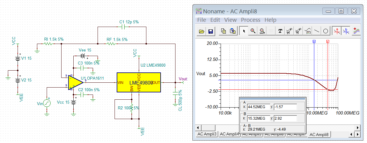
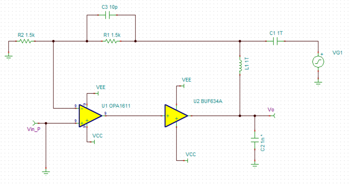
I'm working on a headphone amplifier project that use the circuit recommended in LME49600 datasheet. Only that I've replaced the LME49720 with OPA1612, hoping for better performance, and use 1.5k for both resistor in the feedback loop.

Since headphone cable is likely to add some capacitive loading to the circuit, I've been checking the performance when loaded with capacitor. But it seems that I am having a problem with stability.

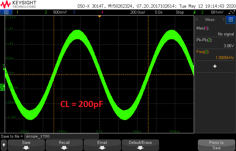
The circuit works fine without capacitive loading. But once I add the capacitive load larger than 200pF, the circuit start to oscillate. The oscillation frequency is about 18MHz.


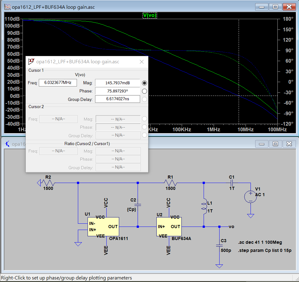
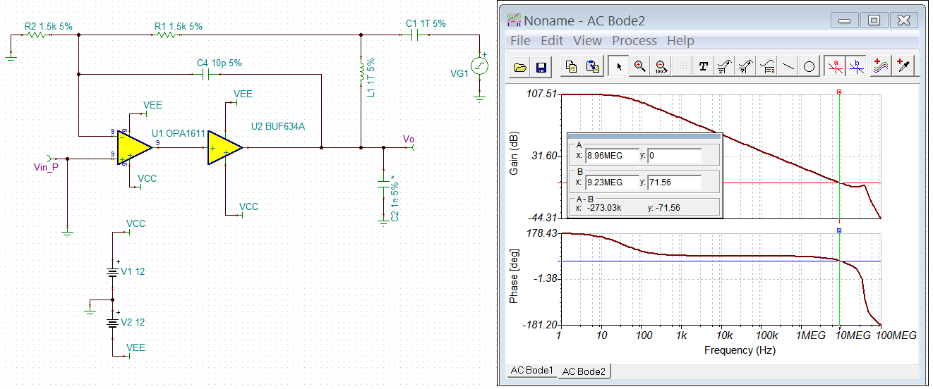
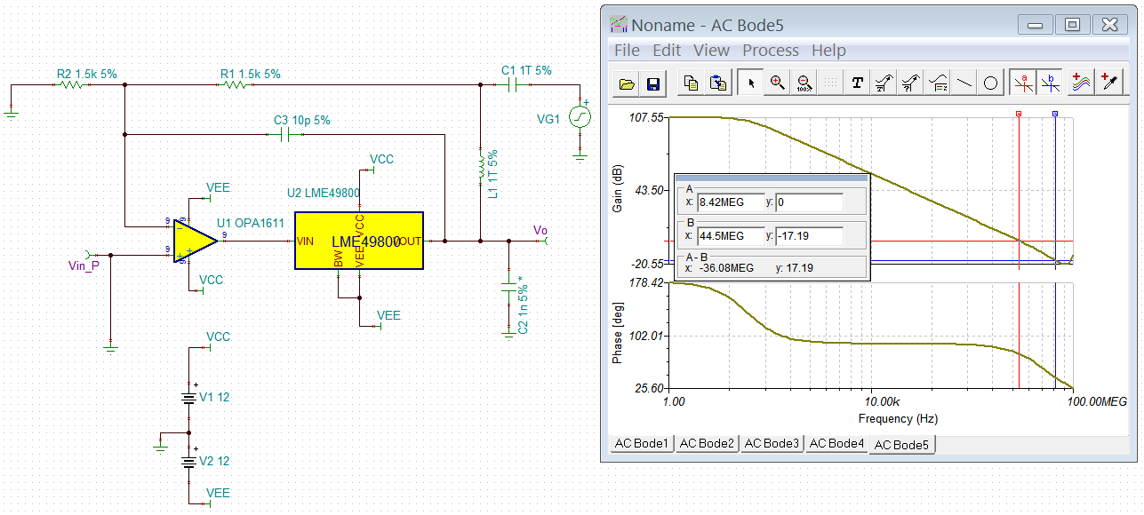
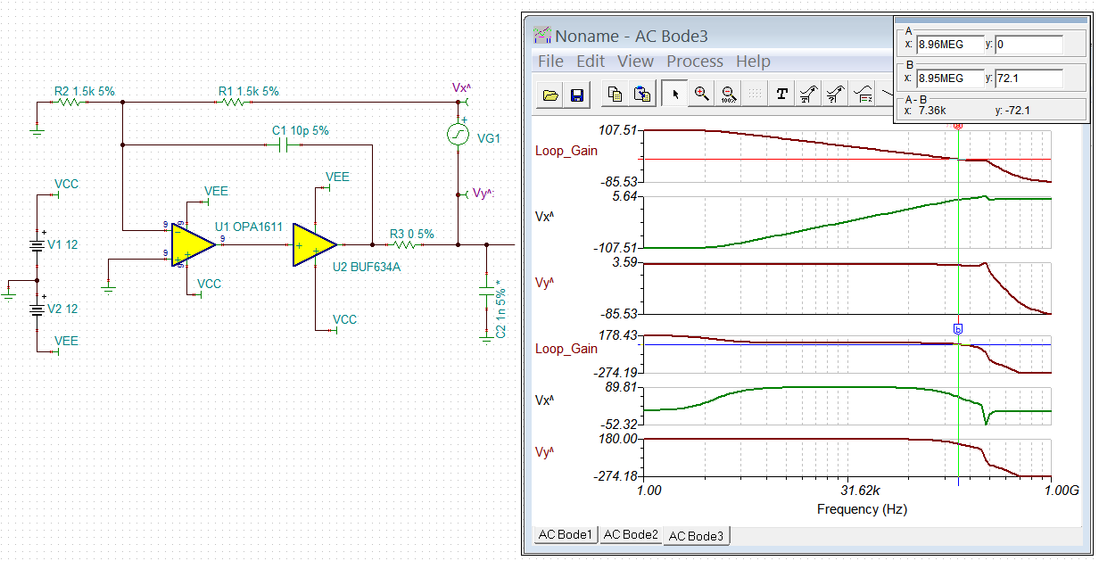
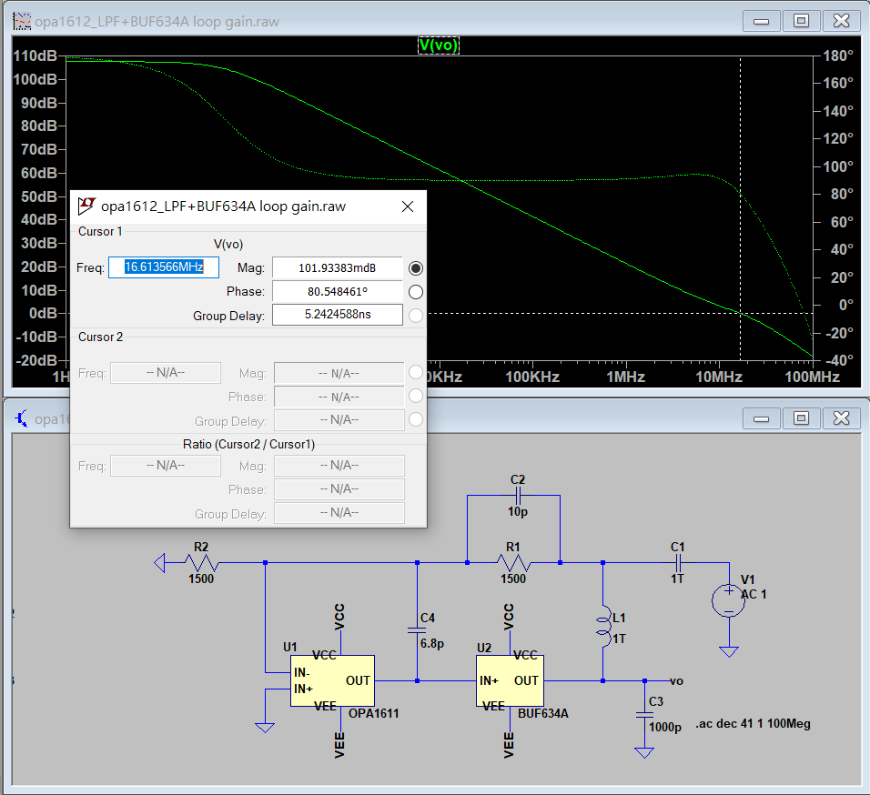
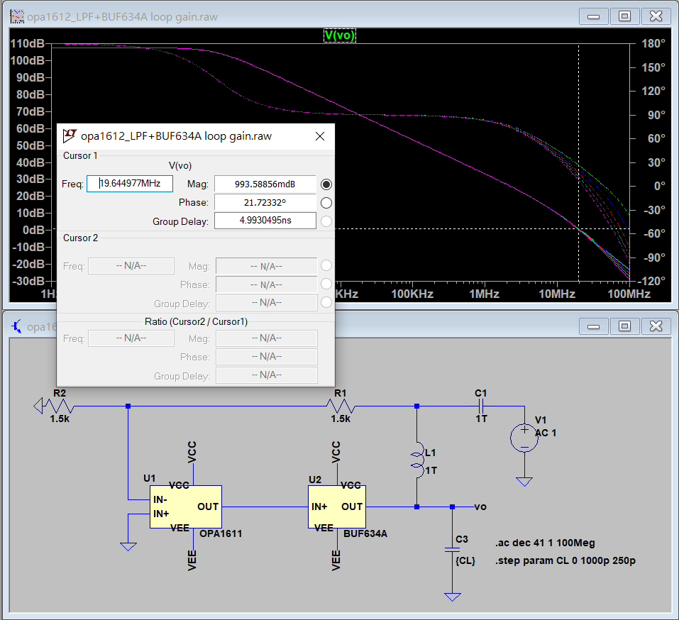
I also run some simulation to check. (The Cload characteristic is not modeled in the spice of lme49600, so I had to use the spice of BUF634A instead, but I assume the behaviors are similar.) Although the simulation shows there is  a PM of 20 degree, but the trend is somehow similar: the PM decrease as capacitive load increases.

While more capacitor is added as loading in actual measurement, the oscillation freq then decreased to 16M, and 14MHz. These results seems quite expected when having such stability problem.

So it seems like the combination using OPA1612+LME49600 is not having enough phase margin for capacitive load. And as far as I know, some headphone cable indeed have parasitic capacitance up to 500pF.

I've also try it out with LME49720 and have the same problem. I'm now wondering if evaluation kit for LME49600 also have the same problem, because I suppose the THD+N performance is measured without capacitve load.

Does the recommend circuit really have this problem with capacitive load? Do you have any suggestion for stability? I would really appreciate it. Thanks in advance!!

  • Hi ,

    There is a pole near the unity gain bandwidth, which is the reason why the op amp circuit is oscillating. 

    Do you have any suggestion for stability? You may need to lower your loop gain and/or reduce your BW of the op amp., and move the pole to the right of unity gain BW by two octave or more.   

    I created the following circuit as an example --> for OPA1612 + LME49600 i

    /cfs-file/__key/communityserver-discussions-components-files/6/OPA1611-_2B00_-LME49800-Audio-Stability.TSC

    Best,

    Raymond

  • Hi Raymond,

    Like I said, the spice for LME49600 does not model the effect of Cload. All the curves are overlapped in a sweep variable simulation in regards to Cload. The spice model for LME49600 is not being useful for this problem. So I use the model of BUF634A instead.

    I kind of get your idea to put a zero around 8MHz at the feedback loop to compensate the output pole. It does show some improvement in PM in the simulation(with spice of BUF634A).

    But in the measurement, it only improves slightly.

    With the original circuit, it starts to oscillate as the Cload is larger than 200pF.

    With a 12pF capacitor is added in the feedback loop, the circuit now oscillates when the Cload is larger than 300pF (and with smaller oscillation magnitude, so some improvement can definitely been seen here). What's surprising is that the oscillation stops as Cload further increase to larger than 600pF. This phenomenon is not seen with the original circuit up to 1000pF. Do you have any idea about this?

    Also, I adopt a circuit topology that I've seen somewhere by adding a capacitor in between the op amp and buffer as below.

    This does improve the stability significantly (somehow, because I actually don't know how the capacitor can lower the dominant pole frequency) for Cload all the way up to 1000pF, however, at the expense of open-loop gain of OPA1612.

    I haven't check the impact on THD with decreased loop-gain. But I expect THD would also degrade. Maybe I'll share it when I get the results.

    For now, it seems to me that the recommended circuit for LME49600 may not be a good solution for headphone application, because it is not able to well handle the capacitance of cable.

    Does this mean that OPA1622, which I haven't try yet, is the only possible solution for headphone application?

    Thanks.

  • Hi ,,

    Please tell me the which circuit that you want to compensate it for you. I know that the circuit I enclosed will not oscillate with up to 500pF capacitive load. The added 12pF compensation capacitor is only applied to my circuit. 

    You have to compensate the pole near the unity gain. As the example you attached, it is still shown a pole near the unity gain, which it will oscillate. You have to move the pole to right of unity gain BW. You need to do the compensation systematically when you are dealing with large capacitive load. If you do the trial and error, it may take a long time.  

    Best,

    Raymond 


  • Hi Raymond,

    I am using just the same circuit as your example. But there is oscillation when CL is larger than 300pF.

    The spice of LME49600 shows no effect  of CL, so it may not be meaningful to use it for simulation.

    loop_simulation_opa1612+lme49600.TSC

    Can you use BUF634A for demonstration instead? How do I move the output pole to the right of unity gain BW?

    loop_simulation_opa1612+buf634a.TSC

    Thanks.

  • Hi ,

    I modified  your compensation and move the zero and pole to the right. It should be ok now. If you have other issues, please let us know.


    Best,

    Raymond

  • Hi Raymond,

    It is very nice of you to do the demonstration.

    But the example looks weird to me. L1 and C1 is there to "break the loop" for loop-gain simulation. They do not exist in real circuit. It doesn't feel right to add any component across it.

    Please tell me if I'm wrong about this.

    So the circuit is actually like the below, which is basically the same as your previous example. And I've already tried it with C3=12pF. It starts to oscillate with CL larger than 300pF. 

    Or maybe I should try out a few different value for the capacitor. After all, I'm using LME49600 in the real circuit. It may be somehow different from BUF634A.

    Thanks.

  • Hi ,

    L1 and C1 is there to "break the loop" for loop-gain simulation.


    1Terahenry and 1Terafarad may not exist in the world. But here is what it does during simulation. 1Th in L1 is to maintain the DC feedback or bias to your your feedback loop, but  it blocks all AC signals (X_L = sL). loop. 1Tf in C1 blocks all DC and pass AC signals. For your real circuit, remove the signal injection VG1 and C1, and short L1, your circuit should work without oscillation.   You should be able to drive the 1nF capacitive load from your microphone now. 

    Here is another way to do loop gain analysis (small signal injection method), where your phase margin in this circuit is shown at 72 degree. Play around your capacitor size in your simulation,  and it should not make significant differences within 10p +/-5p without changing your BW significantly.  

    Best,

    Raymond

  • Hi Raymond,

    "1Th in L1 is to maintain the DC feedback or bias to your your feedback loop, but  it blocks all AC signals (X_L = sL). loop. 1Tf in C1 blocks all DC and pass AC signals."

    I agree with you on this point. But in your simulation setup, isn't 10pF in C1 still in the AC signal loop, rather than blocked by L1?

    I've now come up with the circuit as below. 10pF in C2 improves the PM to some extent. So capacitance in C4 can be reduced from 15pF to 6.8pF, and also reduce the degradation in loop gain.

    This circuit is stable with Cload up to 1nF, and gives a measured THD+N of -115dB at 1kHz for 16ohm@120mW. This number is quite enough for now.

    Btw, what's the advantages of LME49600 over BUF634A? I just noticed that BUF634A seems to have better specification than LME49600, but lower on the price?

    Thanks.

  • Hi ,

    Question:

    But in your simulation setup, isn't 10pF in C1 still in the AC signal loop, rather than blocked by L1?


    I do not know what which C1 of 10pF you are referring to. Do you mean C2 of 10pf? C1 in 1Tf is to block the DC from signal injection in  V1. C2 of 10pF is part your compensation. 

    Question:

    Btw, what's the advantages of LME49600 over BUF634A? I just noticed that BUF634A seems to have better specification than LME49600, but lower on the price?


    Yes, both buffer driver performances look similar. BUF634A is newer designed product for low power application and has wider temperature range. 

    Best,

    Raymond