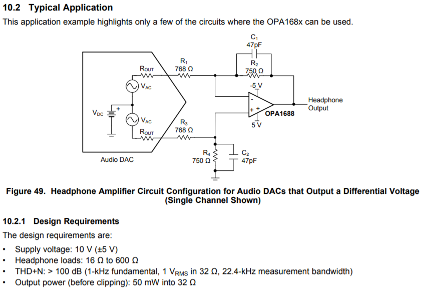
The example circuit in the datasheet suggests a low-pass filter with a cut-off frequency of 4.52MHz.
For a headphone amplifier I went through one of your headphone amplifier design guides and also had a resulting circuit were the cut-off frequency of the low-pass filter had 3.68MHz.
The problem is that the circuit produced a noise-floor of -70dBu to -80dBu throughout the whole audio band. Attached you can find the circuit: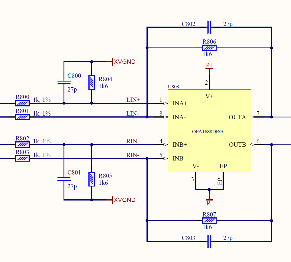
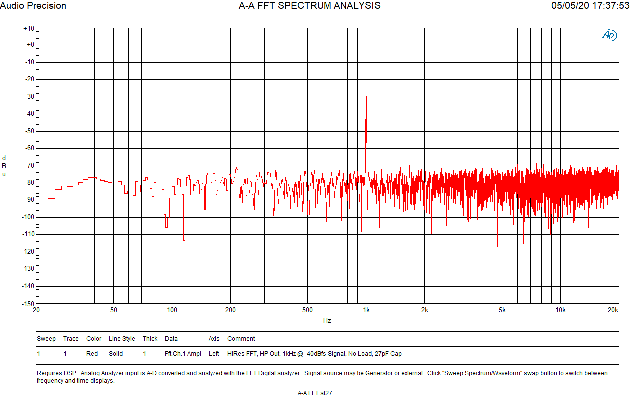
FFT of the circuit with 100k load:
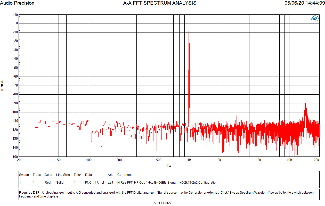
Using 1k6 Ohm for Rf and 2k49 Ohm for Rg and setting all caps to 2.2nF the FFT looks like these, with a peak at 15KHz:
Can you please explain why some of your suggested headphone amplifier circuits use low pass filters with an unusually high cut-off frequency?