This thread has been locked.

If you have a related question, please click the "Ask a related question" button in the top right corner. The newly created question will be automatically linked to this question.

PCM5242: PCM 5242 in software mode / 3-wired mode

Part Number: PCM5242

Hi All:

I want configure PCM5242 in software mode / 3-wired (BCK+LRCK+DATA) due to EMI issue. (Need remove MCK to reduce EMI)

Reference spec: http://www.ti.com/lit/ds/symlink/pcm5242.pdf?&ts=1590142233192

Table 50 shows a recommend clock divider setting for PLL. When the fs = 48kHz the value of   P=1 / J=16 / D=0 / R=2

All registers I set for PLL are:

1. Register 4 = 0x01, (PLL enable)

2. Register 13 = 0x02, (Choose BCK for PLL)

3. Register 14 = 0x10, (Use PLL clock for DAC)

4. Register 20 = 0x00, (P=1)

5. Register 21 = 0x10, (J=16)

6. Register 22 = 0x00, (D=0)

7. Register 23 = 0x00, (D=0)

8. Register 24 = 0x01, (R=2)

9. Register 27 = 0x01, (NMAC = 2)

10. Register 28 = 0x0F, (NDAC = 16)

11. Register 29 = 0x03, (NCP = 4)

12. Register 30 = 0x07, (DOSR = 8)

13. Register 37 = 0x02, (Disable clock auto detection)

But, still can't hear sound output from analog output, is there anything wrong?

Please advise. Thanks

  • Hi James,

    What is the frequency of the BCK? fs×64?

    Thanks,

    Paul

  • Yes, the BCK is always 64×fs.

    Thanks

  • Make sure you are setting standby mode before you configure the device.  Here is an example (note 0x98 is the device address):

    # Enter Standby Mode
    w 98 02 01 
    #Reset
    w 98 01 11
    #Disable clock errors
    w 98 25 7F
    #Set BCK as PLL source
    w 98 0D 10
    #Enable the PLL
    w 98 04 01
    #Set P value
    w 98 14 00
    #Set J value
    w 98 15 10
    #Set D value
    w 98 16 00
    w 98 17 00
    #Set R value
    w 98 18 01
    #Set DDSP
    w 98 1B 01
    #Set DDAC
    w 98 1C 0F
    #Set NCP
    w 98 1D 03
    #Set DOSR
    w 98 1E 08
    #Set IDAC
    w 98 23 04
    w 98 24 00
    #Exit Standby
    w 98 02 00

    Thanks,

    Paul

  • Hi Paul:

    Thanks for the example code, seems the key is register 37(0x25)

    #Disable clock errors

    w 98 25 7F

    Once I disable all the clock error detection, analog output correctly.
    But I don't know why.
    ------------------------------------------------------------------------------------------
    Also, example code has one error, which is register 30(0x1E)
    #Set DOSR
    w 98 1E 08 (X)
    w 98 1E 07 (O)
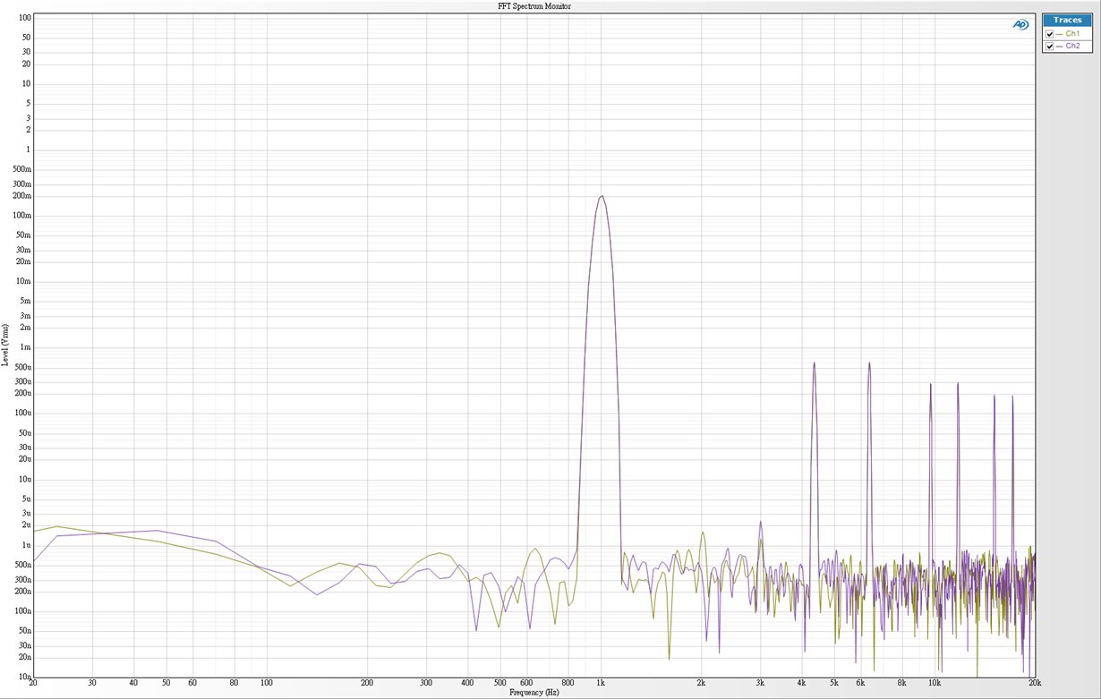
    An incorrect DOSR will cause harmonic while audio output
    Here I test with 1kHz sine tone when DOSR set to 0x08
      
  • Yes, you are correct, DOSR should be 8, meaning the register should be the value 7.

  • Thanks Paul, I think I figured out how to configure PCM5242 in software mode / 3-wired mode:

    There are two approach, please correct me if I am wrong:

    [1. Use clock auto detection]

    //--Step 1: Set 5242 power down and standby mode:

    w 98 02 11

    //--Step 2: Reset 5242 registers:

    w 98 01 11

    //--Step 3: Disable SCK halt detection (3-wired mode, ignore SCK)

    w 98 25 08

    //--Step 4: Set PLL reference from BCK

    w 98 0D 10

    //--Step 5: Enable PLL

    w 98 04 01

    //---Step 6. Set 5242 power up and normal mode

    w 98 02 00


    [2. Configure PLL on your own based on input Fs]

    (Take 48kHz, BCK is 64xFs for example. See Table 50: http://www.ti.com/lit/ds/symlink/pcm5242.pdf?&ts=1590142233192)

    //---Step 1~4 are the same, but step 3 need disable clock auto detection:

    w 98 25 0A

    //--Step 5: Set PLL para: P/J/D/R

    w 98 14 00

    w 98 15 10

    w 98 16 00

    w 98 17 00

    w 98 18 01

    //--Step 6: Set divider of DSP/DAC/CHARGE PUMP/OVER SAMP

    w 98 1B 01

    w 98 0E 10

    w 98 1C 0F

    w 98 1D 03

    w 98 1E 07

    //--Step 7: Set DSP clock cycle in one audio frame

    w 98 23 04

    w 98 24 00

    //--Step 8: Enable PLL

    w 98 04 01

    //--Step 9: Set 5242 power up and normal mode

    w 98 02 00

  • Hi James,

    Both of these methods work, though method 1 does not work with all FS combinations.  In this case, BCK is 64×FS = approx 3MHz, so that is fast enough for the auto-detect to use.  Some slower rates, like FS=16kHz, that would not be the case.  Method 2 is the most surefire way to configure the PCM, but is a bit more complicated, as you know.

    Thanks,

    Paul

  • Hi Paul:

    Thanks for telling me this.

    Fortunately, in out application, we will not face Fs = 16kHz, generally 48kHz~192kHz.

    So auto clock detection will fit our need.

    Thanks,

    James