This thread has been locked.

If you have a related question, please click the "Ask a related question" button in the top right corner. The newly created question will be automatically linked to this question.

DRV595: Output self-excitation in TEC application

Part Number: DRV595

Hi Team,

We use DRV595 as a TEC driver. We are faced with unstable operation of the device with some load. 

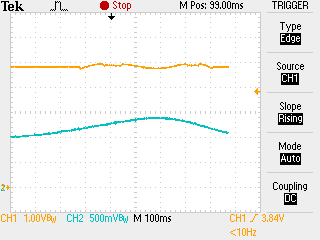
The output fluctuates after reaching target temperature. If the set and measured temperatures are equal, the output starts to fluctuate a few seconds after turning on. 

We use the load with built-in Peltier element and NTC sensor. We can not change or modify internal configuration of the load. 

The device operates perfect with most loads but we have a few cases with fluctuations.

The problem is that there is another TEC controller that works fine with all loads without any changes in setup. Therefore, we cannot tell customers that the issue is the load. The issue is in our TEC driver on DRV595.

The scheme is:

  • VCC = 5V, single power supply operation
  • 1SPW mode
  • master mode, 32 dB gain
  • 400 kHz frequency
  • differential input

We tried to change it did not bring any effect:

  • 600 kHz and 1000 kHz frequency
  • BD mode
  • output filter configuration (increase and decrease inductance and capacitance)

We also tried to swap outputs and differential inputs - no effect.

Decrease in gain has some effect. But even with a grain of 20dB, the circuit goes into stable operation after several minutes. This is unacceptable.

Achieving stable operation in a typical configuration with most of the loads takes a few seconds.

We found that the voltage drop on the problem load is slightly less than on others - 1.7V @ 1A vs 2.1V @ 1A. We added 1 Ohm in series to Peltier element and got a significant effect. In this setup without any additional changes  the circuit goes into stable operation after a few tens of seconds. But we think this is not the best solution. And still, the circuit goes into stable operation much longer than usual.

We also noticed that the GVDD voltage is throbbing when the device fluctuate. We do not know if this is normal.

We can try to change the control scheme to a single-end input, but it will take a much time and require redesign the pcb.

Now we are looking for a simpler and faster solution and we hope for your help. Could there be a problem in the load impedance or in the GVDD voltage throbbing?

Self-excitation of fluctuations when the inputs are equal:

GVDD voltage throbbing:


DRV595 shematic:

  • Hello Andrey,

    Can you capture waveform of your PVCC as well during these abnormal output conditions.

    Best Regard,

    Luis

  • Hello Luis,

    PVCC voltage on the pins of the DVR595:

    Yellow - PVCC, blue - IN-, DC mode 1V/div

    AC mode 20mV/div

    Best Regard,

    Andrey

  • Today I tried to increase PVCC to 12 V, and it did not bring any effect.

  • Hello Andrey,

    Since you say you have issues with the GVDD fluctuations, for the the DRV595 GVDD is generated from an internal LDO that is powered by AVCC. However if your system you are using a single supply configuration the internal LDO is powered by PVCC. Based on your schematic, You don't have any decoupling capacitors on PVCC to deal with high frequency or low frequency noise which is most likely causing or is a potential cause of fluctuations on both voltage rails. Can you try adding the decoupling caps close to the device as shown in the schematic on page 11 of the DRV595 datasheet.

    Best Regards,

    Luis

  • Hello Luis,

    The figure shows a part of the schematic. We have only 22uF X5R caps bank to reduce ripples.

    I added 1000pF and 0.1uF caps close to the chip as shown in the datasheet - the output fluctuations continued, nothing changed.

    We are also not sure whether the GVDD fluctuations is the cause or effect. They appear only at the same time with the output fluctuations.

    Best Regard,

    Andrey

  • Hello Andrey,

    You have only shown the PWM driver circuit - I am wondering if this is caused by an unstable system - the loop might be only marginally stable???

    I comment on this because I consider to use the DRV595 as a TEC driver too and was searching the web for more information about the driver.

    Best regards

    Stefan Hansen

    Denmark

  • Hi Andrey,

    I'm not sure if they are related but I would recommend changing the bootstrap capacitors out to be 220nF capacitance instead of the 470nF you have on there. We design the system around 220nF so it's possible that using 470nF could be causing this issue. 

    I'm also curious if this problem arises in BD mode. If possible could you try that? 

    One last thing I'd like to see is the output before the LC filter to see how that looks when the device reaches stability and starts to exhibit the fluctuation 

    Best Regards,

    Robert Clifton

  • Hi Robert,

    I apologize for the delayed answer. We had to switch to another project.

    I tried 220nF bootstrap capacitors - no effect.

    BD mode also did not bring any effect, I tried it earlier and wrote in the first message.

    I took OUTN (blue) and OUTP (green) signals. If you need other settings, please advise.

    Stable:

    During fluctuations, the picture is unstable, the PWM smoothly changes from the first pic to the second and back:

  • Hi Andrey,

    I understand. I've had that happened to me before. 

    This has given me a chance to think about this and look things over. I have some follow up question:

    - So IN- has a signal at the frequency of 1Hz? 

    - Do you see this issue under an open load? 

    - Can you provide some characteristics of the Peltier Element? Maybe the datasheet? 

    - Have you tried running it without C7?

    Best Regards,

    Robert Clifton

  • Hi Robert,

    - We set a constant signal to IN- through the resistor, after the resistor the signal starts fluctuate.

    - Under open load OUTN and OUTP signals are stable. I probably didn't quite understand the question. If there is no load, then there can be no fluctuations, right?

    - We do not use a discrete Peltier element, we use the load with built-in Peltier element and NTC sensor. So we dont know any characteristics of the Peltier, except absolute maximum ratings of 3A and 4V. Loads that work normally with the device have the same or very similar characteristics.

    - Removing or changing the capacity of C7 has no effect.

    Best Regards,

    Andrey

  • Hi Andrey,

    There can still be fluctuations. The reason I'm asking is to try to isolate where in the circuit path is causing the issue. There could still fluctuations even with no load. It just depends on where in the signal path is causing the fluctuations. 

    It might be easier to discuss this further offline to go into more detail in your system. 

    Best Regards,

    Robert Clifton

  • With no reply from the OP, it is assumed to be solved.  This thread will be closed.