This thread has been locked.

If you have a related question, please click the "Ask a related question" button in the top right corner. The newly created question will be automatically linked to this question.

PCM3168A: Incoming values not saturating correctly

Part Number: PCM3168A
Other Parts Discussed in Thread: PCM3168

Hello all,

When driving the PCM3168 ADC inputs with an out of range value, I expect it to saturate at the extreme values. Specifically, if I overdrive the input I expect to see values that span from 0x800000100 to 0x7FFFFF00. Instead, on the high side I see an occasional glitch like the following. The input source is a triangle wave. Line 65 should be another 0x7FFFFF00 but it's not. Sometimes when going above the top of the range, one or more values will be random instead of full scale.

What am I missing? Background information below.

I'm using single sampling mode at 48kHz. Format: TDM 24 bit left justified. 

I've tried switching the input HPF on and off. I've tried inverting the phase. I've tried attenuating the ADC signal. I'm getting good results when I keep the signal in bounds, but glitching when exceeding the range on the upper end. Yes, it would be possible to clamp the signal in the analog domain. I accustomed to one of your competitor's parts that handles this circumstance gracefully.

Thank you for your help.

Aaron Higgins

  • Hi Aaron,

    This is not a behavior we have observed with this device before. I have a few questions to clarify your setup and the observed results:

    1) What voltage are you overdriving the input to and what is your power supply?

    2) Do you still see this behavior if a DC voltage is applied?

    3) Is the value you see in the glitch fairly consistent, or completely random? Does it tend to occur during the same portion of the waveform?

    Of course this could be resolved as you have mentioned by clamping the signal, and I would recommend doing this anyways from a protection standpoint to make sure you are not damaging the device.

    Thanks,

    Zak

  • Thanks for the response.

    The supply on the PCM3168 is 3.3V for Digital and 5V for the analog side. I did try a DC level and saw similar results.

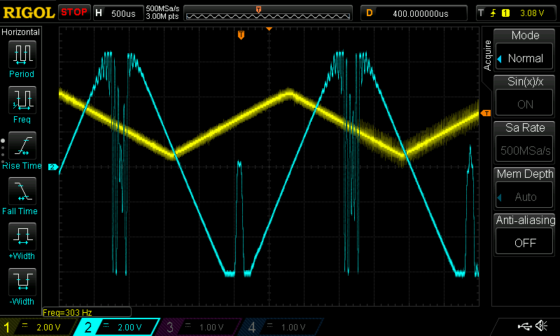
    The incoming values seem glitchy when they should be saturated. In the above, the yellow waveform shows the signal on the VIN1- pin. I am using differential inputs, so there is a similar, opposite signal on VIN+. The blue represents the output in digital loopback mode. I would expect these values to saturate--not wrap like they do.

    To my eye, the VIN waveform is +/-2V centered on 2.5V. Which is outside of of the recommended operating conditions--but within the absolute maximums.

    The recommended operating conditions say to use 1Vrms for single ended and 2Vrms for differential. Should I interpret this to mean that each side of the differential should be 1Vrms?

    Does this mean the upper and lower bound of the ADC are at  Vpeak of 1.414V?

    Where would you recommend setting the clamp values for best results?

    Thank you

    Aaron Higgins

  • Hi Aaron,

    Can you confirm that your input is truly balanced? What are you using to drive the inputs? This codec does not have a PGA front end so it is necessary to have an input stage with sufficient drive capability. This almost looks like the phase reversal behavior that can occur in some opamps when the input common-mode is exceeded. 

    Can you also share the behavior when a DC voltage is applied to the inputs? Does this occur when the common-mode moves out of range, or only when the differential signal is excessively large? 

    Your interpretation of the inputs is correct, each input can tolerate 1Vrms swing, and differential operation effectively doubles the input range. Typically we recommend setting the clamp values above the max recommended operating point but below the absolute maximum rating to prevent damage. However, in this case that will offer protection, but not resolve your issue unless you want to throw away some of your signal swing.

    Best,

    Zak

  • I'm using a circuit derived from the datasheet to generate an AC coupled differential input. One thing I did notice is that C136 should be 22pF. I believe this is a truly differential circuit and what I see on IN0_P and IN1_N are phase inverted from each other and centered on VCOMAD (ADC_VMID in my schematic).

    I don't have an easy way to drive one input with a DC value--short of modifying a PCB. I do have another design that is DC coupled on the inputs. I can run some tests there if you like.

    I did some experimentation and found the following:

    • Full Range of ADC values: Each side of differential pair has Vrms of 1V, Vpk of 1.4-1.5. This sounds like the recommended values to me.
    • Overswing with valid, clamped values  Each side of differential pair has Vrms of 1.2V, Vpk of 1.75V
    • Overswing with bad, wrapping values: Each side of differential pair has Vrms of 1.4V, Vpk of 2 V

    It other words, there is a pretty narrow range between full scale and bad data. Given that the absolute maximums are +/- 2.8V assuming a 5V analog supply, I was hoping for more room to work.

    Perhaps the best way forward seems to be reducing the input gain further to avoid the out of bounds range. The input clamp should keep the signal in check. If there is some other approach that you recommend, please let me know.

    Thank you very much

  • Hey Aaron,

    I apologize for the delay, I wanted to recreate this and it took me some time to create my own setup. I'm able to recreate the same behavior that you are seeing though on one of our test boards and it seems pretty clear that this is a behavior inherent to the part and not the result of a bad IC or something like that. What I have seen is that the distortion increases dramatically as you approach full scale until eventually it begins to clip and then oscillate. Once this instability starts, the overflow flag triggers, indicating that the full scale range has been exceeded. I have also seen that this tends to happen around 1.3Vrms as you have observed. 

    If you want to eliminate the problem then I agree you will have to limit the input signal range as you have described and clamp around the 1.3-1.4Vrms signal level to avoid the oscillation condition. Alternatively, you could use the overflow flag to detect when this condition has occurred and discard/mute the data if this flag has been triggered.

    Best,

    Zak

  • Zak,

    Thanks for taking the time to check it out. I appreciate your insights.

    Aaron