This thread has been locked.

If you have a related question, please click the "Ask a related question" button in the top right corner. The newly created question will be automatically linked to this question.

TAS6422-Q1: tas6422-q1 i2c have no acknowledge

Part Number: TAS6422-Q1
Other Parts Discussed in Thread: TAS6424

I used a dsp to control and transmit audio to tas6422 .but the warn pin was pulled lower .so I want to write data control to the register through i2c but tas6422 did not respond. The response signal is high level. I have checked the circuit related voltage voltage is normal pvdd And vbat voltage is 12v vdd is 3.3v i2c pull-up resistance is 4.7k ohm .Is this chip broken?Is the driver wrong? But I use this program to control the gyroscope can indeed communicate normally.I feel so confused!
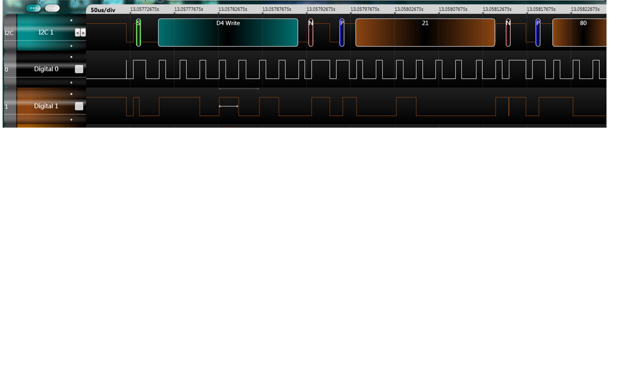
  • Yi,

    As long as 3.3V is ready, IIC interface will be ready. So please check below:

    1. confirm ADDR pin logic

    2. SDA should be toggled at fall edge of SCL, and SDA will be sampled at rise edge of SCL.  while in the waveform above, SDA is toogled at rise edge of SCL, there could be problem with SDA sampling. May you use oscilloscpe to confirm the waveform. or simply change IIC's SDA toggle time?

    Dylan

  • thank you for your reply


    This is the case.


    1. I have determined that both address lines are grounded so that there should be no problem with address errors.


    2. I readjusted the i2c driver,My supervisor suggested to me to modify the duty cycle, so I did it, but the result is very bad,


    this is the modified waveform


    The problem is that i got an acknowledge signal, but the warn pin is still pulled low


    In addition, I can't read the data of the register in the chip. Will it not operate the chip at all?


    I am very humble to ask you and look forward to your guidance

  • We look forward to your reply!

  • Hi Yi,

    I suggest you can check the timing according to datasheet 7.6 Timing Requirements and 9.5 Programming.

    And disconnect I2C interface to other devices, only connect to TAS6422.

    Regards,

    Derek

  • First of all thank you for your reply


    The previous i2c driver I used is simulated by gpio port

    Now I can operate normally with hardware i2c, which is very strange


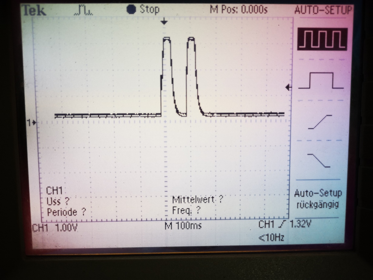
    The current waveform is very strange, My intention is to emit a 4kHz sine wave.no matter what data is input, the output waveform is two sine-like waves, period <10Hz


    I measured the i2s signal input to tas6422 with an oscilloscope
    FSYNC (high)-(low)
    SDIN1 16bits —— 16bits
    fs=48kHz sck = 32*fs = 1.548MHz mclk = 12MHz

    But in theory
    sck = 32*fs = 1.536MHz
    mclk = 256*fs = 12.288MHz

    My settings for tas6422
    Address = value
    0x14 = 0xff,
    0x15 = 0x00
    0x16 = 0x10
    0x21 = 0x80
    0x00 = 0x80,
    0x01 = 0X02,
    0x02 = 0x12,
    0x03 = 0x53,
    0x04 = 0x05,
    0x05 = 0xcf,
    0x06 = 0xcf
    0x26 = 0x47

    Below is my waveform

    Regards,

  • Hi,

    You can read the registers 0x0F~0x14 to check if any fault happened. 

    For 0x03 register, the input format should be  100: I2S (16-bit or 24-bit).

    Regards,

    Derek

  • Dear Derek


    Thank you for your suggestion


    In addition, I would like to ask if you can measure the waveform if the load is open.


    My test method is that the oscilloscope probe is grounded on one side and v+ on the other.

    Regards,

  • Hi Yi,

    You can measure the waveform if the load is open, but only on TAS6424 side.

    If no load, there will be no current, so check on V+ side is not corret.

    Regards,

    Derek

  • Dear Derek

    I want to ask


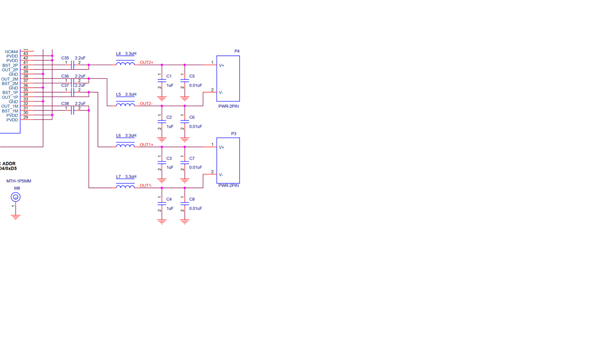
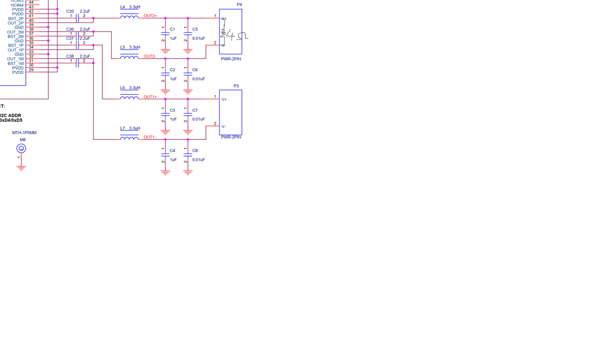
    Can I connect a 4 ohm resistor between V+ and gnd to measure?


    I don't know if it would be dangerous


    Thank you

  • Hi Yi,

    You can connect 4ohm load between V+ and V- to measure signal.

    Connect V+ to ground with 4ohm resistor may have short Fault.

    Regards,

    Derek

  • Dear Derek,


    I connect a 4 ohm resistor between v+ and v-


    Connect the probe to v+ and v-


    But the oscilloscope is not displaying the signal


    The value of the 0x0f register is 0xd4


    CH1 STATE REPOR is 11: DC load diagnostics


    CH2 STATE REPORT is 01: Hi-Z


    It's very strange. I obviously wrote 0x05 in 0x04 and tas6422 has ack signal

    I do not know what to do


    Thank you for your help

  • In addition, I read other values are normal


    especially


    The value of register 0x0c is 0x00;

  • Hi Yi,

    Did you connect all channels with 4ohm load?

    Please dump all register value to us.

    Regards,

    Derek

  • Dear derek

    Reset it again
    The following is the value of the write operation. The writing order is as follows


    Register  ——————  Value

    0x14  ———————— 0xff
    0x15 ———————— 0x00
    0x16 ———————— 0x10
    0x21 ———————— 0x80
    0x00  ———————— 0x80
    0x01 ———————— 0x02
    0x02 ———————— 0x12
    0x03 ———————— 0x54
    0x04 ———————— 0x05
    0x05 ———————— 0xcf
    0x06 ———————— 0xcf
    0x09 ———————— 0x01
    0x26  ———————— 0x40

    The following is the value read from the register


    Register———————Value
    0x00 —————— 0x00
    0x01 —————— 0x02
    0x02 —————— 0x12
    0x03 —————— 0x54
    0x04 ——————0x00
    0x05 —————— 0xcf
    0x06 —————— 0xcf
    0x07 —————— 0xcf
    0x08 —————— 0xcf
    0x09 —————— 0x01
    0x0a —————— 0x11
    0x0b ——————0x11
    0x0c ——————0x00
    0x0d ——————0x00
    0x0e ——————0x00
    0x0f ——————0x55
    0x10 ——————0x00
    0x11 ——————0x10
    0x12 ——————0x00
    x013 ——————0x00
    0x14 ——————0x00
    0x15 ——————0x00
    0x16 ——————0x00
    0x17 ——————0x00
    0x18 ——————0x00
    0x1b —————— 0x00
    0x1c—————— 0x00
    0x1d —————— 0x00
    0x1e —————— 0x00
    0x21 —————— 0x00
    0x22 —————— 0x01
    0x23 —————— 0x14
    0x24 —————— 0x00
    0x25 ——————0x00
    0x26 ——————0x40


    The result is still no signal


    hoping to get your help

  • Hi Yi,

    0x02 register should be 0x62---according to your application, Fsw should be 2.1MHz;

    0x09 —————— 0x01--- you disable DC diag, so the DC load diag register did not report error.

    From the 0x11 register, there is clock fault! You need to check the MCLK and TDM timing.

    Regards,

    Derek

  • Dear Derek

    Thank you for your patience in helping me
    It really touched me
    thank you for your reply


    I use I2S


    The following data input signals were measured

    COFS = 48.44kHz

    I see the following in the manual


    The MCLK clock must not be in phase to sync to SCLK. Duty cycle of 50% is required for 128x FSYNC, for 256x and 512x 50% duty is not required


    So I chose MCLK as 128x FSYNC

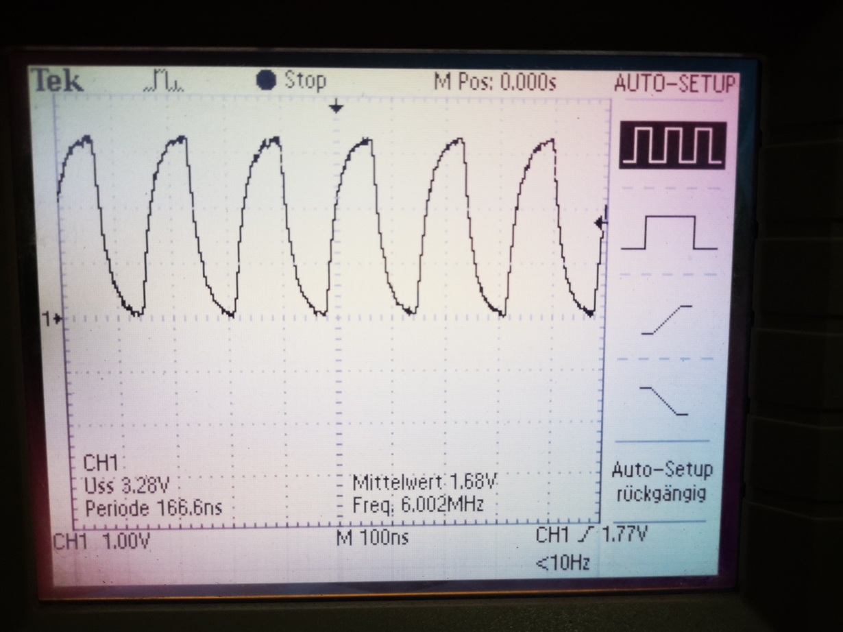
    The MCLK frequency I measured is around 6.01MHzZ

    This is the waveform

    Regards,

  • Hello, I would like to ask is this clock normal?

  • Please check 0x11 register if any clock fault happen

    Regards,

    Derek