This thread has been locked.

If you have a related question, please click the "Ask a related question" button in the top right corner. The newly created question will be automatically linked to this question.

TAS5720A-Q1: TAS5720A-Q1 overheating problem

Part Number: TAS5720A-Q1

I drive 2 TAS5720A-Q1 IC and both of two have overheating problem that starts after I connected analog voltage. Even speakers are in mute, power dissipation on IC's are so high and I get Over Temperature Error.

How it is possible ?

  • Several things to be confirmed:

    1. How did you operate TAS5720A-Q1 into Mute? Software mute (which still has PWM output) or Hardware mute (no PWM output)?
    2. Measure SPK_OUT+, SPK_OUT-, BSTRP+, BSTRP- waveform to check whether output PWM is correct.
    3. Check PVDD current while mute to trigger OT protection.
    4. Verify thermal pad soldering to PCB board.

    Regards

  • In datasheet; there is a phrase for Left and right volume register, "Any setting less than 00000111 places the channel in Mute" and I applied this. I did not control power control register to put device in Mute. Shoul i do ?.

    When master sends me 0 volume value. I send a value less than 7 to mute device and recude power dissipation, but no matter what I do.

    No mute pin on IC for driving by IO operations. Only allows to control by controlling registers.

    My thermal pad soldering design is weak but even it was good, I am sure it will not be enough.

    Although I do not start to operate IC to drive speaker, there is a heating over IC's. When I disconnect the Analog supply, devices are cooling.

  • Hi Ismail,

    From the discussion above, it appears that the device is driving current without any audio signal modulation the output.  Therefore, we must look for other conditions that can cause current flow in the output stage power FETs.  This is the only stage of the device that can cause significant heating.  The one area that I also look at is the LC filter.  I see that you are using a 68uH inductor with a 470nF capacitor.  The inductor can saturate and cause the heating you are experiencing.  One way to test, is to remove the 470nF capacitor and see if the heating is reduced.  If you find that this is the case, the inductors need to be replaced with proper ones.

  • Thanks for reply, Firstly, I disconnect the speakers and output LPFilter cap. and shorted inductor. Problem is still ongoing, warming up somehow. I am thinking this problem may be related switching loss of FET's ? 

     In this case, IC is not pass any test.

  • Ismail,

    Please reply to items 2 and 3 in the response above.  Repeated below.

    2.  Measure SPK_OUT+, SPK_OUT-, BSTRP+, BSTRP- waveform to check whether output PWM is correct.
    3.  Check PVDD current while mute to trigger OT protection.

  • PWM was correct and duty cycle was varying  depending on sound. 

    I will inform you current driven by IC in case of triggering OT protection.

    By the way, I have one MCU to control two IC which drives same digital data.

    Can I control these two IC from one I2S channel(same digital sound data will be used) ?

    In practice, one of  two ICs is playing bad. It has output pwm but this pwm could not modulate. Duty cycle was not changing like the other one.

    All I2S connections and other passive components design are identical between each other.

  • First of all, two TAS5720A-Q1 in your system should be configured as different I2C address. For SPK_SLEEP/ADR pin, one device is pulled down with address 0xD8, another device is pulled up with address 0xDA.

    Two devices could be able to reuse same I2S line. The key is to check whether different I2C address and separate configuration is done.

    As for the 'hot issue', is able to measure chip case temperature? What's more, please help to provide below waveform. It could help us for further analysis.

    2.  Measure SPK_OUT+, SPK_OUT-, BSTRP+, BSTRP- waveform to check whether output PWM is correct.
    3.  Check PVDD current while mute to trigger OT protection.

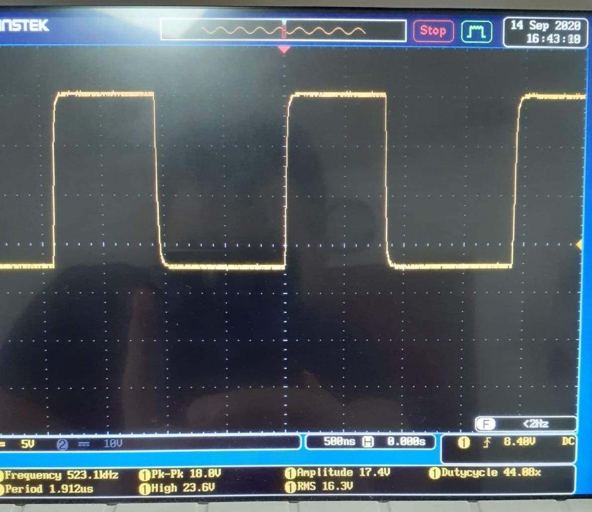
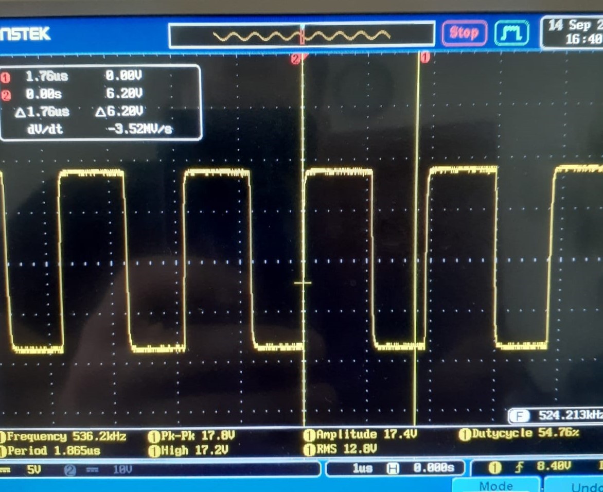
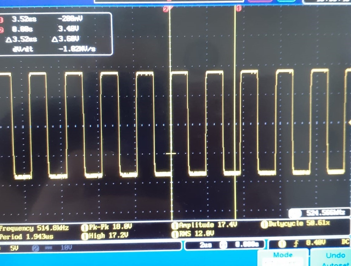
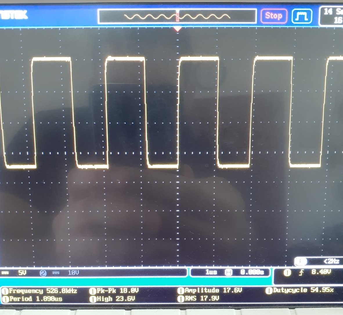
  •  SPK+ SPK- BSTRP+ BSTRP-

    These photos are belong to my TAS5720AQ1, spk+,spk-,bstrp+,bstrp- respectively.

    Vsupply=18VDC.

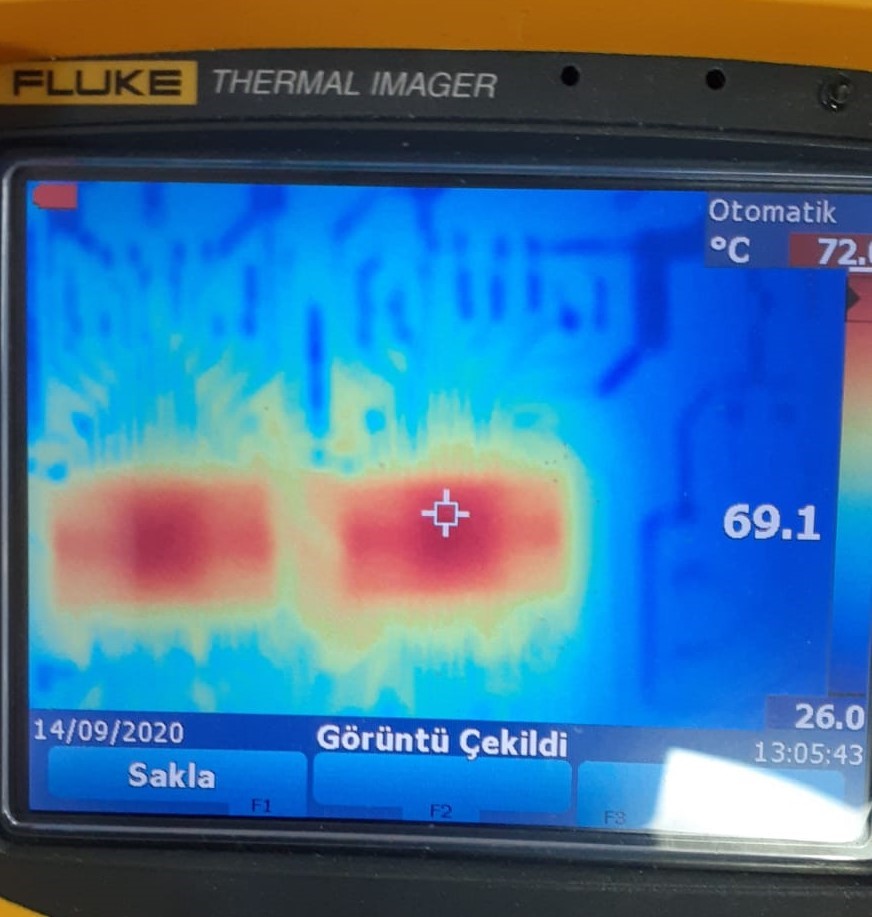
    Ianalog @ triggering OT in Mute= 70mA, Temperature @ Mute= 69.1 C

  • Hi,

    What's the PWM frequency (waveform shows ~529.2kHz) configuration? Whether it is configure as 12*Fs (44.1kHz)?

    The thermal picture seems two devices are well set into play mode. Does 'one device issue' still happen?

    69.1C case temperature should not trigger OT protection. Previous OTP happens at this situation?

    One more check item, please share us the schematic and PCB layout. We could use offline email due to private data sharing.

    Regards 

  • 	TAS5720AQ1_comm_param.DigitalClipper=		        0;//clipper için ayar yapılmadı!
    	TAS5720AQ1_comm_param.AnalogGain = 			AnlGainSettingIs_25dB;
    	TAS5720AQ1_comm_param.ChannelSelect = 		        LChSelected;
    	TAS5720AQ1_comm_param.DigitalBoost = 		        Boosted_0dB;
    	TAS5720AQ1_comm_param.HPFilter = 			HPFilterIsNot_Bypassed;
    	TAS5720AQ1_comm_param.PWMRate = 			SwRateIs_16LRCK;
    	TAS5720AQ1_comm_param.SerialInputFormat = 	        Default_I2Sformat;
    	TAS5720AQ1_comm_param.SpeedMode = 			SingleSpeed;
    	TAS5720AQ1_comm_param.VolumeFade = 			VolumeFade_Disabled;
    /************************************************************************************/
      hi2s3.Instance =             SPI3;
      hi2s3.Init.Mode =            I2S_MODE_MASTER_TX;
      hi2s3.Init.Standard =        I2S_STANDARD_PHILIPS;
      hi2s3.Init.DataFormat =      I2S_DATAFORMAT_16B;
      hi2s3.Init.MCLKOutput =      I2S_MCLKOUTPUT_ENABLE;
      hi2s3.Init.AudioFreq =       I2S_AUDIOFREQ_32K; //32Khz
      hi2s3.Init.CPOL =            I2S_CPOL_LOW;
      hi2s3.Init.ClockSource =     I2S_CLOCK_PLL;
      hi2s3.Init.FullDuplexMode =  I2S_FULLDUPLEXMODE_DISABLE;
    /************************************************************************************/
    

    I do not know how to do private data share.

    Firstly, in idling, there is no triggering, It's written wrong by me. It triggers as current gets bigger.

    But, even no triggerring in idling. 70 C is quite high in room temperature. You know standarts..

    Both of two ICs have overheating issue. Analog input comes from over C7.

    VDD comes from after L4 common mode.

    Check my idle state power dissipation calculations:

    70ma^2 x (4ohms/perspeaker)=0.02 W

    65 K/W x 0.02W = 1.2 K+25= 26.2 C (ıt must be)

    in real 70 C.

  • Ismail,

    It appears that you have no ground plane to dissipate any heat from the TAS5720A-Q1.  Do you have a ground plane?

  • I will re-draw that footprint, add holes and more ground plane, but I am not sure problem will be solved by doing this.

    They are 70 C @ Mute. Did you see any mistake except poor grounding ?

  • Ismail,

    Your schematic is correct for both device.  Without any pcb copper to remove the heat, a 70C temp would not be unsual.  The heat is actually trapped between the device and the pcb fiberglass material on your pcb.

  • Thank you Gregg, I will make my ICs relax by expanding ground. I will inform you about results.