This thread has been locked.

If you have a related question, please click the "Ask a related question" button in the top right corner. The newly created question will be automatically linked to this question.

OPA1637: Some observations on PDS info

Part Number: OPA1637
Other Parts Discussed in Thread: PCM1795, , OPA1611, OPA1652, OPA1632, THS4561, TLV320ADC5140

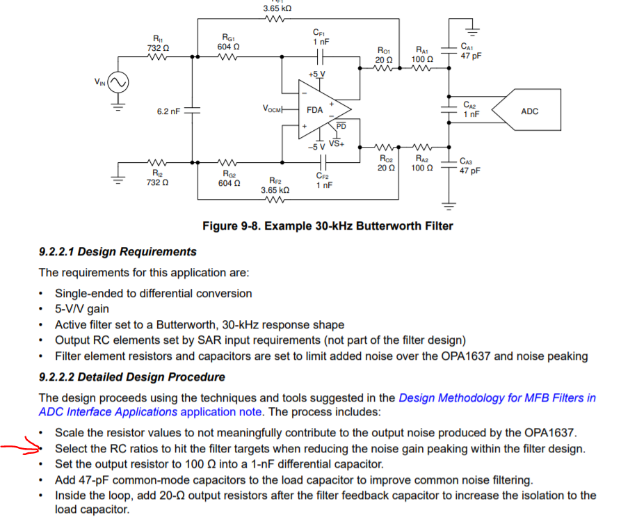
Starting to review this more recent audio FDA, 

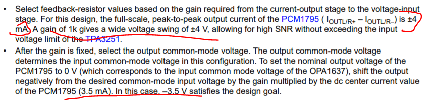
On this app circuit, I certainly get the CM level shift issue, but there is a inconsistency between the stated Vpp implying a 4mA midscale and the level shift comments stating 3.5mA midscale, 

I personally would have targeted a DAC output CM voltage 0.5V to get a little away from the ESD diodes, the text states 0V, which if the midscale is 4mA out of each side, the Vocm needs to be -4V - not a big deal, but just a little detail, 

  • Hi Michael-san,

    In my calculation, I could not see the contradiction between fig.38 of PCM1795 datasheet and the section 9.2.1 of OPA1637 datasheet...
    Could you please review the simulation files in as below?

    PCM179x+OPA1637FLT03.TSC

    PCM1795Fig53.TSC

    Best regards,
    Iwata Etsuji

  • The way you have that first FDA file set up is fine, if the DAC avg output current is in fact 3.5mA. But, in that section of the datasheet, it says this - 

    The way I read that 1st piece is the avg current is 4mA not 3.5mA, to get +/-4mA on each side. I have not looked at the DAC datasheet, but if it is 4mA, just need to set Vocm into the FDA at -4V, with a differential swing around that - hence the -10V supply. 

  • Morning Iwata-san, 

    I went on in the OPA1637 data sheet to the MFB circuit which is the same as the THSP210 example, I read a little closer and noticed a reference to my old app note (pretty good at the time, I have moved beyond this quite a lot from this old work) - it says the flow reduces the NG peaking, actually not as described in the attached file, 

    And here is some detailed review and redesign for slight improvement, 

    8030.Some review on the MFB filter in the OPA1637 datasheet.docx

  • Incidentally Iwata-san, 

    The MFB tool I have developed over many years gets improvements every once in awhile as I have time and interest. A relatively recent update got a lot more analytic on setting the required minimum GBP to pick parts. I went ahead and published that approach in this article. The old filterpro tool (circa 1989) that generates the TI filter tool RC numbers really kind of guessed on the required min GBP, 

  • Morning Iwata-san, 

    Moving pretty quickly now on this next AX article on small improvements to the circuit in the OPA1611 Figure 53, 

    This alternate device table will show up in there somewhere - starting with the two OPA1611 Zt stage, moving on in ascending quiescent for suitable >+/-5V supply capable FDA's, 

  • Hi Michael-san,

    I will attach the analog output specification of PCM1795 in its datasheet.

    As you can see in the this figure, the center current (common mode output current) is 3.5mA, and the differential output current is +/-4mA.
    I had referred this to make the attached simulations.

    Best regards,
    Iwata Etsuji

  • Hi Michael-san,

    Thank you for sharing your article.

    I agree the old filter pro was a good tool.
    Now I'm using Webench and some hand calculation ( I had calculated and represented the  MFB-FDA-LPF (with the Aol and the output impedance) in 3rd order rational function and it could be simplified in the well-known 2nd order rational function  when Aol --> infinity. ) 
    When I need some phase margin analysis, I'm referring to a TIPL
    The below schematic is my modified MFB-LPF with OPA1637 for an audio ADC.

    OPA1637Bessel-LPF+ADC2.TSC

    As you can see in this schematic, I believe OPA1637 helps for engineers to choose higher resistor values freely due to its low input current noise.

    So I still would like to comment OPA1637 has the lower input current noise (and low 1/f noise) than the prior generation in your table...but as you pointed out, the input current noise is not dominant in the differential transimpedance circuit, especially low transimpedance gain case...How about very high input impedance of OPA1637; 1Gohm/1pF?

    By the way, I suppose OPA1652 seems to be wrong in your table, i.e. it's OPA1632.

    Best regards,
    Iwata Etsuji

  • Anyway, here is what your design is generating - pretty aggressive, I calculate you need 19MHz GBP to get a min LG of 20dB for this design, the OPA1637 is only 8.5MHz, but my GBP adjust routine can predistort the RC values to account for that, 

    Here I have reset the R's much lower to get more into the OPA1637 noise region, solved for lower NG peaking and made small R adjustments to fit better for this low GBP solution, That integrated noise plot (looking across the output pins) shows the significant improvement. The super high input Z on the OPA1637 is a don't care for transimpedance design as I need a large C anyway across the inputs of the THS4561 to improve phase margin, 

  • Sorry Iwata-san, 

    I was putting your RC values in for an ideal op amp, I think you have adjusted them to hit the measured results, I should have started with those - good job, 

  • morning Iwata-san

    If I look at fig. 38 in the PCM data sheet, that curve says the midscale is 3.5mA with +/-3mA around that. I got to thinking, if you say it is is +/=4mA, does that mean if flips polarity by 0.5mA, probably not and the curve shows 3mA which makes more sense

  • Let me try this filter question again, your file name says Bessel and simulation shows 417kHz, 

    To get that (Fo and Q wise) Filterpro tells me I need this, where now the min GBP required for 20dB min LG is pretty close to the device numbers. Ignore the peaking numbers, since its bessel there is no peaking but the solutions are missing that apparently

    Putting the adjusted RC values into your schematic again gives the desired bessel at about 420kHz F-3dB, 

    This will be quite a lot lower noise than what you sent simply due to resistor noise being lower

    Here is that integrated noise to the output pins comparing the RC values you sent to this newer solution

  • Hi Michael-san,

    I'm sorry for delayed response.

    Regarding the full scale range of PCM1795, the table 2 in its datasheet shows the negative output shows +FSR=-5.5mA and -FSR=-1.5mA, on the other hand the positive output shows +FSR=-1.5mA and -FSR=-5.5mA. Therefore, I consider PCM1795 has +/-4mA differential output and its midscale is equal to -3.5mA.

    While, regarding my MSB-LPB schematic, I supposed the high input impedance required audio AUX input and OPA1637 conveys it to audio ADC (such as TLV320ADC5140) with 786ksps HiRes sampling. So I selected the higher resistor value than 1kohm and set the cut-off frequency in 400kHz.
    As you pointed out, it seems to be slightly aggressive design with respect to its phase margin...

    Best regards,
    Iwata Etsuji

  • Ok Iwatao-san, that makes sense, the DAC is 3.5mA out with +/-2mA around that each side.