This thread has been locked.

If you have a related question, please click the "Ask a related question" button in the top right corner. The newly created question will be automatically linked to this question.

TLV320AIC3104: Amplitude rise on a codec loopback test

Part Number: TLV320AIC3104

Hi,

We have noticed an increase of the amplitude measured when we made a loopback test on the component TLV320AIC3104.
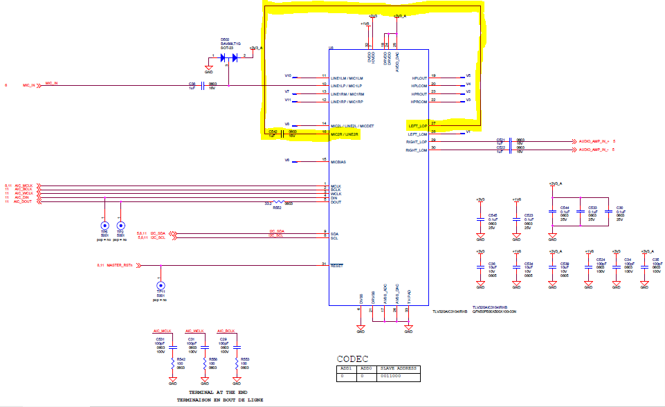
For our loopback test, as you can see on the next picture (highlighted in yellow), the MIC2R/LINE2R input pin (pin 16) is connected through a 1uF capacitor to the LEFT_LOP output pin (pin 27).

Every time we make this validation on our equipment, we play separately three wave at three fixed frequency (400Hz, 1kHz and 7kHz) and we measure for each wave played the amplitude, the frequency, the SNR and the SINAD. Only the amplitude have increased and all other parameters measured are still correct.  

The next picture shows you the evolution of the amplitude measured in time : 

As you can see when we have an amplitude under 10000 (i do not know the unit) until the middle of 2017, we are now often above 10000.

I do not find a root cause for this problem as neither our design nor the tests have change since the beginning. Besides as the tests is a loopback test, my only remaining lead is that the gap we have here is caused by the TLV320AIC3104 component himself.

However I did not find a change in the datasheet of the component that could permit to explain this behaviour and that is the reason why I need some help from you to try to find an explanation for my issue. 

Thank you for your support.

Matteo

  • Hello Matteo,

    The X Axis is the year the test was performed? As for the Y Axis, you said that you do not know the unit but I would like to first understand what is actually being plotted. 

    Regards,

    Aaron

  • Hello Matteo,

    Following up, I would like some more information on how the amplitude test is being conducted. You say a wave is being played and then the amplitude is being measured. Is there a fixed amplitude form the wave or is the amplitude being adjusted and you are recording the maximum amplitude? Some more background on how the test is conducted would be really helpful. Thanks!

    Regards,
    Aaron 

  • Hello Aaron,

    First, thank you for your answer.

    In order to help you to understand my issue, I would like to add some context and give you more details about this test. 

    The equipment is tested on a test bench. All the tests made on the equipment is driven by a test sequencer where I only have access to all the functionalities that are tested and to the PASS/FAIL criteria for each test. I do not have access to the test method because the test sequencer uses DLLs … and unfortunately I do not have access to the source code of those DLLs.

    For the test that interests us, the amplitude of the wave is fixed as the frequency. I don't have the information about the type of wave but I assume that the wave is a sine wave. So, the amplitude measured is constant as the amplitude of the wave is fixed.

    The values on the Y axis is most likely a digital value for the amplitude at the output of the codec. All the points you see on the graph is the amplitude value measured on a different serial number of the equipment. It is not a test we make on an identical equipment through time. The important thing to retain about this graph is not the fact that we have different amplitude values for each serial number but the fact that all the amplitude values measured have increased since 2017 and even more since 2019.

    I have made some investigation and I can confirm you that : 

    • We have not change the design of the equipment (hardware or software) since 2014 and the TLV320AIC3104 has always been the component used for the codec in our design
    • The test method has also not changed in time

    I perfectly understand that all the information I give you are a little bit confusing and not as precise as I would like it to be but for now I cannot give you more information because unfortunately I do not have them. 

    Finally, I would like to only focus on the component AIC3104 and ask you a question about it: 

    Are there some parameters that could have an impact on the amplitude measured at the output of the codec as for example the gain error ? 

    Thank you again for the support.

    Best Regards,

    Matteo

  • Hello Matteo,

    I really appreciate the detailed information you provided. This gives me more insight on how the test may be performed and how data was collected. 

    As for your question, Gain Error is most likely the culprit and what I was suspecting in the beginning. There are many reasons that gain error may change over devices such as the types of material used and where the device was fabricated at that time. I cannot go into too much detail on this but it is not uncommon to see this type of behavior as realistically, not all devices are made at the same time with all the same material properties. 

    Regards,

    Aaron

  • Hello Aaron,

    Thank you for the explanation about the possible impact of the gain error.

    If as you said the gain error is the cause of the increase we have noticed it means that the only thing we can do is to adapt our test tolerances in order to take into account of this variation.

    In the datasheet I only find nominal values given for the gain error. Is there some kind of minimum and maximum value for the gain error ?

    Best Regards,

    Matteo

  • Hi Matteo,

    The reason we don't have a min/max gain error value in the data sheet is that these devices aren't precision devices and we don't trim for gain error. The value in the data sheet is a typical one as you mentioned but we have seen it as high as 1dB - 1.2dB.

    Regards,

    Aaron

  • Hi Aaron,

    Ok I understand it better now.

    So the fact that the gain error is higher implies that the amplitude of the signal we are going to measure will also be higher right ?

    I would like to talk again the amplitude values we measured. As I previously said, it seems to me like it is a digital value that is recorded during our test.

    Is it possible that the values measured are the values at the output of the internal ADC of the component ?

    I ask you that because after looking again to the functional block diagram of the component I have a thought about the way our loopback test is made : 

    • The DSP that communicate with the codec send the command for the loopback test via the DIN input (pin 4) 
    • The internal DAC converts the digital signal in an analog signal which comes out of the AIC3104 on the LEFT_LOP output (pin 27)
    • The external loopback make this analog signal enter in the AIC3104 on the MIC2R/LINE2R input (pin 16)
    • Then, the signal is converted by the internal ADC and we send data to the DSP via the DOUT output (pin 5)

    Do you think that my interpretation is consistent or it is totally wrong ? 

    Thank you for your support.

    Best Regards,

    Matteo

  • Hello Matteo,

    I believe your understanding about the effect of gain error is correct. I guess to put this in perspective, If we have an output code of lets say, 3000 and a gain error of 0dB. That would mean that the output code of 3000 is a true code. As we increase this gain error, that output code of 3000 will represent a higher code and therefore, seem like a higher signal level that what is actually provided. 

    As for the measured ADC output, it is completely possible that those are output codes but it would be interesting to see what the DAC input is. Do you know if it is a Full scale input? Full scale DAC output is 2Vpp or .707Vrms so if that was recorded we could use that do see what went into the input of the ADC. If it is a full scale input, then am not sure what those recorded ADC values are. If using 16-bit data, which is the minimum resolution, then a full scale output code is roughly 32768 (Not including any gain error). The plot you showed has values at around 10000. 


    Regards,

    Aaron

  • Hello Aaron,

    Thank you for your answer, it helps me a lot to understand what happens in our system.

    The DAC input is not a full-scale input. The command line sent for the test mentioned an input volume of 25 and an output volume 80. I believe that permits to control the amplitude of the input and the output signals.

    Since last week I am trying to have more information about all the missing things that could permit us to understand perfectly the issue but I did not found something on the DLLs code which pilots the test sequence. I am currently trying to find if something interesting is present on the software of the equipment.

    I will come back to you if I found something interesting to share with you.

    Thank you again.

    Best Regards,

    Matteo

  • Hi Matteo,

    Glad I could help! I have marked this as TI Thinks Resolved and will close the thread. Please respond to reopen the thread if you have any more questions. 

    Regards,

    Aaron