This thread has been locked.

If you have a related question, please click the "Ask a related question" button in the top right corner. The newly created question will be automatically linked to this question.

PCM1802: Replacing PCM1803A with PCM1802

Part Number: PCM1802
Other Parts Discussed in Thread: PCM1803A,

Hi,

Are there any concerns if replacing PCM1803A with PCM1802?
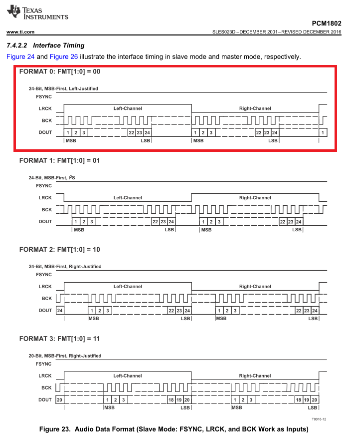
Is my understanding correct that FSYNC pin should be pulled-up to VDD with the slave mode(FMT1=0, FMT0=0, MODE1=0 and MODE0=0) for PCM1802?

Best regards,
Kato

  • Hi Kato-san,

    I don't see any concerns moving from PCM1803A to PCM1802. In slave mode FSYNC is an input pin that is used to enable the shifting of data out of the device. Sort of like an enable specifically for the ASI bus. You can keep this pin high if you always want the device to output audio data.

    Best,

    Zak

  • Hi Zak-san,

    Thank you for the information.

    I would like to confirm just in case, but should FSYNC be controlled such as the following master mode?
    It seems that the noise is output from DOUT if FSYNC pin is kept to be pulled-up to VDD.

    Best regards,
    Kato

  • Hi Zak-san,

    Sorry for rushing you.

    Could you please tell me whether PCM1802 can normally work by pulling up FSYNC pin to VDD in slave mode?

    Best regards,
    Kato

  • Hi Kato-san,

    My understanding is that in master mode the FSYNC signal is used to define where the data ends. So even though your LRCK may have a 32-bit width, the FSYNC pin indicates where the last data bit is (since the device only transmits up to 24 bits). This is not a convention that is commonly used in I2S systems, usually the FSYNC/LRCK are synonyms for the same pin. In slave mode, as per the diagram, you should be able to tie the FSYNC pin high if you do not wish to gate the data.

    Best,

    Zak

  • Hi Zak-san,

    Thank you for the additional information.

    I understand.

    Best regards,
    Kato