This thread has been locked.

If you have a related question, please click the "Ask a related question" button in the top right corner. The newly created question will be automatically linked to this question.

TAS2557EVM: Audio forum

Part Number: TAS2557EVM

Hi Expert,

I checked below post and still have some questions regarding the effect of the power up/down sequence. 

1. would you please explain more what does "faults at internal level shifters and/or diodes being forward biased" mean? 

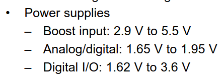
2. about IOVDD, is this a range we can use 1.62-3.6V or  it has to be either 1.8V or 3.3V?

3. "the supplies should at least power down at the same time", the "same time" here means AVDD, DVDD=1.65 and IOVDD=1.62V? For IOVDD using 3.3V, the power down timing is still considered 1.62V or 3V? 

4. does our EVM also follow the sequence? Since we couldn't tell it make the sequence design on the circuit. 

Thank you.

Allan

  • Hi, Allan,

    Our team will take a look at this and will provide an answer as soon as possible.

    Best regards,
    Luis Fernando Rodríguez S.

  • Hi Allan,

    Let me comment on your questions below:

    • There was a typo on the other e2e thread, I meant to say "reverse biased" and this is basically that a circuit is powered inversely to what it is supposed to be powered. There is some internal level shifter circuitry that could be stalled if powered sequence is not correct.
    • The typical values for IOVDD are 1.8V and 3.3V. However we suggest a range for each of these typical values, hence we provide a min and max for 1.8V and a different set for 3.3V. We do not recommend to use IOVDD between 1.98V and 3.0V as this range could meet some issues recognizing "high" and "low" states.
    • Yes, the sequence is the same regardless of the value of IOVDD voltage
    • EVM is most likely powering up/down the supplies at the same time.

    Please let me know if this helps and if you have any further questions.

    Best regards,
    -Ivan Salazar
    Applications Engineer - Low Power Audio & Actuators

  • Hi Ivan,

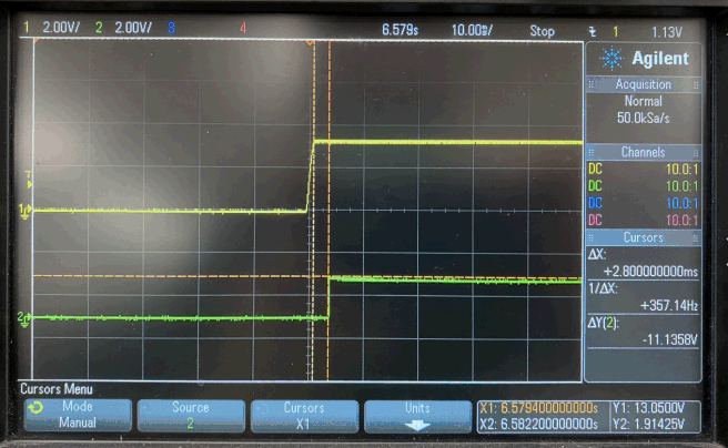
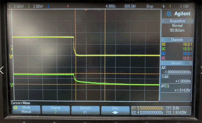
    Could you clarify is the power up/down waveform good? Note that 1.8V(AVDD=DVDD) is converted from 3.3V(IOVDD) so when power down, IOVDD would power down earlier about 13ms.

    yellow: AVDD=DVDD=1.8V

    green: IOVDD=3.3V

    power down zoom in (the delta timing is compared at the dropout moment)

    Regards,

    Allan

  • Hi Allan,

    You can proceed with the power sequence form EVM, if you're intended to use this sequence.

    Most of our devices are tolerant to different power sequences, but we still have to provide a suggested power sequence for reference.

    Best regards,
    -Ivan Salazar
    Applications Engineer - Low Power Audio & Actuators

  • Hi Ivan,

         Thanks for your reply. I still have some questions as below. Please help me to clarify them.

    1. I can understand this chip have tolerance for power on/off sequence. I believe that is why the design of EVM cannot meet this sequence. Could you tell me the exactly number about the tolerance of power on/off sequence?

    2. You said some internal level shifter circuitry that could be stalled if powered sequence is not correct. Is your mean that may cause logic issue? If the logic issue is occured when system powr on, I think it is a problem. When the system off, this logic issue should not cause any problems. Is that right? 

  • Hi Freedom,

    Unfortunately there is not a specified tolerance value for the time or current. The suggestion is to keep the sequence based on the data sheet spec in order to stay safe, as mentioned the device is tolerant and thus the EVM is working OK, however since the performance is closely related to each design specific values, a tolerance cannot be specified.

    The answer is, the EVM design can be followed as is. However if design will be different from EVM, we encourage to follow the power sequence as specified in the data sheet.

    Best regards,
    -Ivan Salazar
    Applications Engineer - Low Power Audio & Actuators

  • Hi Ivan,

        Thanks for your reply.

    About question1, as you said, the device is tolerant and EVM is working OK. So the sequence is fine for EVM. Could you tell me what kinds of test ned to do to confirm this sequence is in the tolerance of the chip?

    About question2, I just want to know what purpose for power off sequence. As you said, "internal level shifter circuitry that could be stalled if powered sequence is not correct" but it should not cause any problems if all system is power down. if my unstandarding is correct, can we ignore the power off sequence?

  • Hi Freedom,

    This is being followed up over email, I'll post the same information here:

    If device is able to respond I2C transactions, and playback works is OK, then device operation should be considered OK.
    A failure behavior would be unable to communicate through I2C, and since the device is not configured the playback would not be working either.
    I would not suggest tolerance; as mentioned: the EVM is working OK and if customer is planning to use the exact same design, they could consider it. But for any other case I encourage to follow the power sequence from data sheet.
     
    Power down is also specified in data sheet, so I would suggest to follow as well. However in this case, the current peak I mentioned about reverse-bias would not be a problem because the capacitors are already charged.
    To be clear, there is more tolerance during power down, but still following data sheet recommendations is the safest way to design.

    Best regards,
    -Ivan Salazar
    Applications Engineer - Low Power Audio & Actuators