This thread has been locked.

If you have a related question, please click the "Ask a related question" button in the top right corner. The newly created question will be automatically linked to this question.

TAS5760M: SPK_FAULT signal is asserted low

Part Number: TAS5760M

Hi All,

I have a question about TAS5760M.

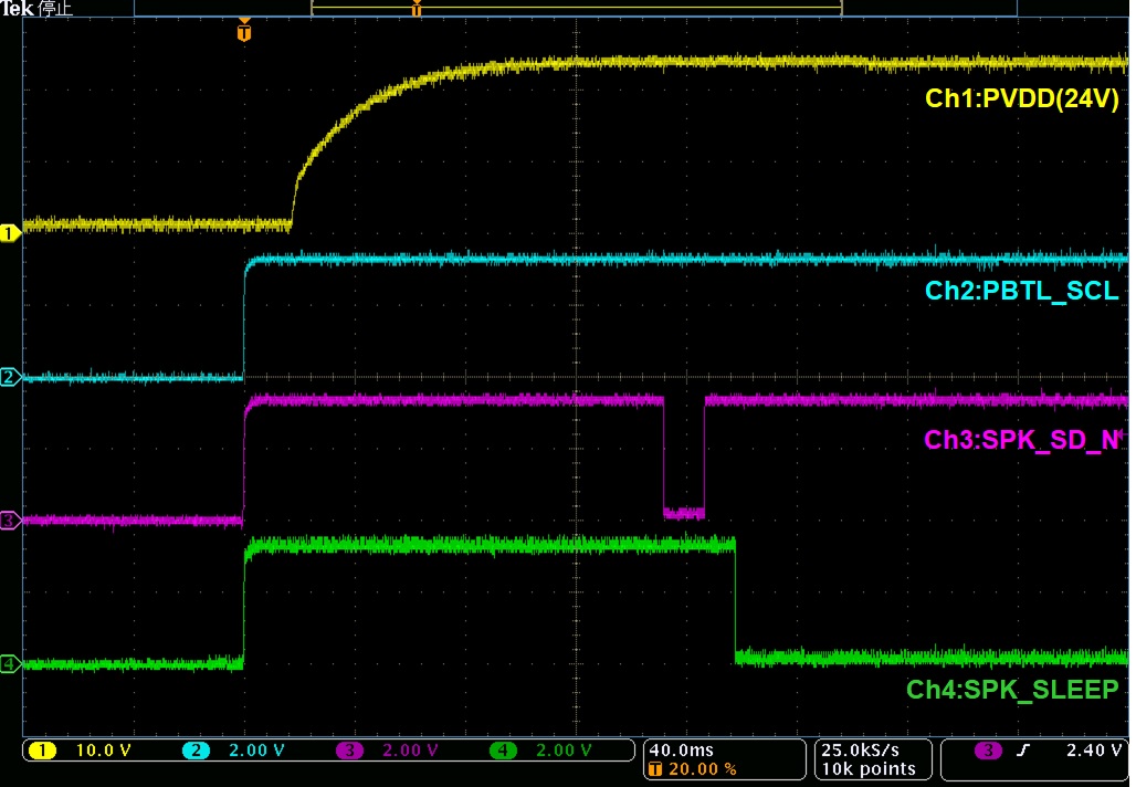
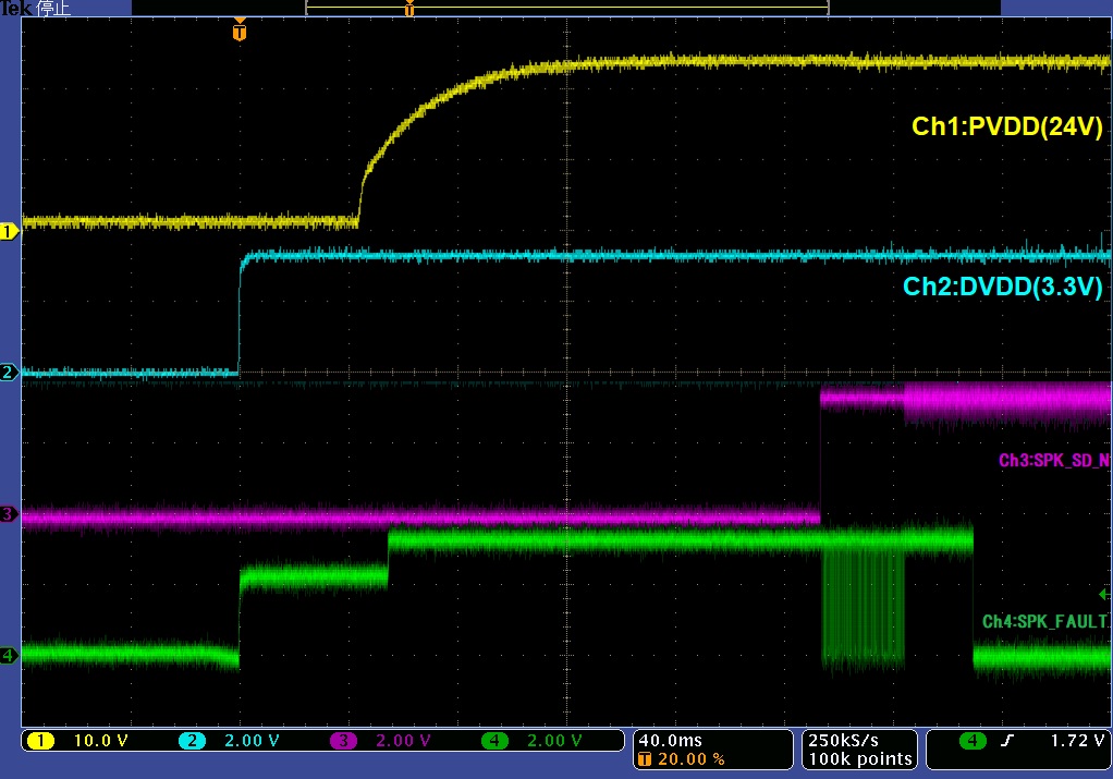
In rare cases, the SPK_FAULT signal is asserted low when the power is turned on at low temperatures.

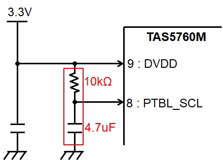
Customer designed PBTL mode with hardware control, but it seems to be booting in BTL mode.
The SPK_FAULT signal is likely to be asserted low because an overcurrent error has occurred due to an output short circuit.

So I have a question.

I confirmed e2e.(e2e.ti.com/.../626902)
In the following sequence, DVDD and PVDD will start up and POR will operate.
If the Configuration pin is stable after 100-250ms, you can read each status.
Is this understanding correct?

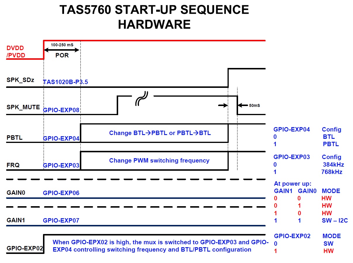
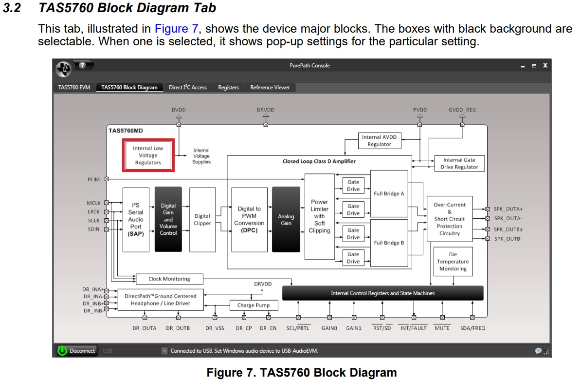
Also, which of DVDD and PVDD triggers the POR?

When driving a POR circuit, the Slew Rate of the power supply may be an issue.
Are there any restrictions on the slew rate of the power supply?


Best Regards,
Ishiwata

  • Hi Shuji-san,

    I think this timing diagram means the hardware configuration detection is completed within 100-250ms after a POR event.

    POR is power on reset that happens on the all the power rails get ready.

    Thanks!

    Regards,

    Sam

  • Hi Sam-san,

    Thank you for your answer.

    I have an additional question.
    Were there any cases such as startup failure when operating at low temperature?

    Best Regards,
    Ishiwata

  • Hi Ishiwata-san,

    For the IC itself, as listed on the TAS5760M datasheet, the device recommended operating condition is "-25C<Ta<85C".

    Within this temperature range, the device should be fully functional.

    Thanks!

    Regards,

    Sam

  • Hi Sam-san,

    Thank you for your reply.

    The customer said it would malfunction at -10 ° C.
    Have you ever had such a report?

    Best Regards,
    Ishiwata

  • Hi Ishiwata,

    Sorry but we don't have similar cases before...

    Does it happen in every board, or has a failure rate? 

    Regards,

    Sam

  • Hi Sam,

    Thank you for your reply.

    I'm asking the customer, that it is every board or failure rate.

    I have additional questions.

    (1) Does the POR time (100-250 msec) change between low temperature and high temperature?

    (2) I think you can change the PBTL and FRQ settings before SPK_SDz is released.
    Can I change the PBTL and FRQ settings?

    (3) If SPK_SDz is released during the POR period, will the PBTL setting be High or Low?


    Best Regards,
    Ishiwata

  • Hi Ishiwata-san,

    1) It should be within the spec under full temperature range.

    2) Yes, you should be able to change the settings when SPK_SDz is low.

    3) Users should not operate the device in such timing. Violating the timing requirement may lead to unpredictable result.

    Thanks!

    Regards,

    Sam

  • Hi Sam,

    Thank you for your reply.

    The question in (3) is, after releasing SPK_SDz during the POR period, does the PBTL pin change to High or Low.
    I'm not trying this. I'm asking which way the device will change.
    The customer does not knowingly set High and Low.
    Does the PBTL pin change to High or Low?

    Best Regards,
    Ishiwata

  • Hi Ishiwata-san,

    Understood.

    The recommended operation for hardware mode PBTL is to set the PBTL/SCL pin in high level before pulling up the SPK_Sdz. It's just an input pin which can't reflect the BTL/PBTL status.

    Thanks!

    Regards,

    Sam

  • Hi Sam-san,

    Thank you for your reply.

    The customer told me not to present the waveform.
    Therefore, it will be withdrawn once.

    I have an additional question.

    Your answer is "PBTL and FRQ can be changed when SPK_SDz is Low", but after confirming the hardware settings, I think it cannot be changed.

    Once SPK_SDz is set to High normal operating state.
    After that, if you set SPK_SDz to Low again and put it in the shutdown state, is it possible to set the PBTL pin?

    Also, I have a question in the content of the answer the other day.
    My way of hearing about (3) was wrong.
    If I unlock SPK_SD during the POR period, is it in PBTL mode or BTL mode?

    Best Regards,
    Ishiwata

  • Hi Ishiwata-san,

    Most devices which support hardware mode starts to detect the hardware configurations once the SPK_SDz is pulled high and latched the settings until next shutdown. For hardware applications, the relative controlling pins voltage should be fixed and not changed after SPK_SDz pulled high.

    Sorry I don't have a proper setup for bench verification on this... But you can remove the LC filter and easily validate this behavior on your board by observing the PWM switching on the OUTPUT pins.

    Please let me know if you have any other questions. Thanks!

    Regards,

    Sam

  • Hi Sam-san,

    Thank you for your reply.

    Does that mean ”PBTL and FRQ can not be changed when SPK_SDz is Low.”?


    Regarding (3), I would be grateful if you could verify it.

    Best Regards,
    Ishiwata

  • Hi Ishiwata-san,

    I was trying to say that, typically the hardware settings (including PBTL and FRQ) can be changed when SPK_SDz is low. The detection was done and configuration locked on the positive edge of SPK_SDz.

    I'm sorry but I don't have a proper board for the bench verification... Could you please do this on your board? It should not be complicated on your hardware designed board.

    Thanks!

    Regards,

    Sam

  • Hi Sam-san,

    Sorry for the late reply.
    Thank you for your answer.

    The customer has done various verifications.

    The PBTL_SCL pin is pulled up by DVDD with 10kΩ.
    PBTL_SCL goes High as soon as the DVDD boots.
    In this state, sometimes it doesn't work..
    SPK_FAULT is asserted Low.

    If a 1.0uF capacitor is attached to the PBTL_SC pin, SPK_FAULT will not go low.
    It works correctly.
    If you slow down the input of PBTL_SCL from DVDD, it works correctly.

    I think there are restrictions on the input of DVDD and PBTL_SCL. Are there any restrictions?
    And why does this happen?
    I would like to know the mechanism that causes problems when using such a startup sequence.


    Is it a problem to attach a capacitor to the PBTL_SCL pin as a countermeasure?
    Can I install a capacitor?

    Best Regards,
    Ishiwata

  • Hi Ishiwata-san,

    What's the SPK_SD# status when DVDD applied? Does it tied to DVDD via a pull up resistor?

    Could you provide a waveform of DVDD, SPK_SD#, PBTL_SCL, and the SPK_OUTA+?

    Thanks!

    Regards,

    Sam

  • Hi Sam-san,


    PBTL_SCL has been pulled up to DVDD (3.3V).

    The waveform is as follows.


    If PBTL_SCL does not have a capacitor, SPK_FAULT is asserted Low.

    If PBTL_SCL have a capacitor, SPK_FAULT is High.

    PBTL_SCL starts up normally when it starts up with a delay.

    Best Regards,
    Ishiwata

  • Hi Ishiwata-san,

    The key point is, the SPK_SD# should be held low for a few milliseconds(5ms should be good enough).

    This is because, if SPK_SD# and DVDD are tied together, when SPK_SD# ramp up to logic high, internal circuits powered by DVDD could be not ready yet, resulting in incorrect mode detection. Long story in short, it's a common timing issue in hardware mode, that users should only enable the amp after DVDD is ready.

    Thanks!

    Regards,

    Sam

  • Hi Sam-san,

    Thank you for your reply.

    Check the waveform below. SPK_SD is set to Low for 5msec or more.
    SPK_FAULT is still asserted to Low.


    Do you know the cause of this issue?


    Best Regards,
    Ishiwata

  • Hi Ishiwata-san,

    I just noticed that, the POR timing shown in previous diagram saying that the duration is 100~250ms. Thus the 5ms delay was not a reasonable number, but should be >250ms. You may take another try.

     BTW, as the phenomenon was FAULT pin went low, I'm wondering if there any real fault. Your configuration is PBTL, if the hardware mode detection was not executed normally, let's say the device is still running BTL, of course an OC fault will be triggered. I'm thinking probably you can just change it to BTL(on output stage, remove the inductors may be the easiest way). If with your current timing, it never triggered the fault flag in BTL, then we can isolate the issue as incorrect configuration detection in hardware mode.

    Thanks!

    Regards,

    Sam 

  • Hi Sam-san,


    Thank you for your reply.

    There is no waveform, but SPK_FAULT is asserted to Low even if SPK_SD is lowered for 250msec or longer.

    Setting PBTL_SCL to High later than DVDD does not cause any issue.
    Are there any restrictions on the input timing of PBTL_SCL and other control pins?
    Is it necessary to keep PBTL_SCL Low during the POR period as in the timing chart?


    Best Regards,
    Ishiwata

  • Hi Ishiwata-san,

    PVDD and DVDD is required to be ready first, meanwhile, the hardware pin configurations including PBTL_SCL(pull up or pull down) is ready as they are referring to the DVDD.

    After POR time, say 250ms, pull the SPK_SD# high, the device should entered the Hardware mode.

    Does this corelate to your condition?

    I don't think keep PBTL_SCL Low during the POR period is a must. If it's a must, then it actually in opposite to the purpose to use hardware mode, because it still requires a GPIO toggling.

    Thanks!

    Regards,

    Sam

  • Hi Sam-san,

    Thank you for your reply.

    Even if DVDD and PTBL_SCL are started at the same time, it works normally, but in rare cases it does not work properly.

    I think POR may not work properly. Please tell us your thoughts.

    The customer also solved the problem by installing a 10kΩ pull-up resistor and 4.7uF on the PTBL_SCL pin.
    In this case, it works normally without failure.
    Is there any problem with installing a 10kΩ pull-up resistor and 4.7uF on the PTBL_SCL pin?
    Please check.

    Best Regards,
    Ishiwata

  • Hi Ishiwata-san,

    Based on current test results, I agree with you that the issue is related to the POR and hardware mode detection. Could you explain that how SPK_SD# configured? Is it derived from DVDD or a GPIO?

    There is no problem to add a R-C filter to insert a delay between PBTL and SCL.

    Thanks!

    Regards,

    Sam

  • Hi Sam-san,

    Thank you for your reply.


    I don't know how SPK_SD is configured. Do you know if you have a schematic?


    I have additional questions. I'm sorry for the many questions.


    (1)There is a difference in the PBTL / SCL pin between the hardware mode reference circuit on the datasheet and recommend Power-on sequence.
         Customers are asking for their views on this difference.

         In the recommended power-on sequence, the PBTL / SCL pin goes low during the POR period, which is inconsistent with the schematic in the data sheet.
         Please tell us your opinion

    (2)Also, Will problems occur if PBTL and FRQ are only pull-up processing?


    (3)In the TAS5760M internal block diagram, there is "Internal Low Voltage Regulators" at the end of the DVDD input.
         Is there a regulator related to the PBTL / SCL pin?


    Best Regards,
    Ishiwata

  • Hi Sam-san,

    I am waiting for your contact.
    (2) and (3) could be confirmed by another E2E.
    Please contact me with the answer in (1).

    Best Regards,
    Ishiwat

  • Hello Ishiwata-san,

    For Hardware Control mode for Mono PBTL, the schematic on the datasheet where PBTL is pulled to HIGH at startup is the expected and recommended behavior.

    Best regards,

    Luis

  • Hello Luis-san,

    Thank you for your reply.

    I'm also aware that both sequences normal operating.
    However, sometimes a fault is detected when the customer starts PTBL/SCL from High.
    Should we recommend this startup sequence as a workaround?


    Best Regards,
    Ishiwata

  • Hi All,

    I have been waiting for your reply, but have not heard from you.
    Could you give us a response?

    Best Regards,
    Ishiwata

  • Hi Ishiwata-san,

    Apologize the late response.

    The "recommended start up sequence" actually shows the sequence implemented on the EVM. The hardware control pins are connected to the GPIOs. In my understanding, the mode detection is initialized by SPK_SD# pulled up. 

    Adding a capacitor on PBTL/SCL pin is an acceptable workaround.

    Thanks!

    Regards,

    Sam

  • Hi Sam-san,

    Thank you for your reply.

    "Adding a capacitor on PBTL/SCL pin is an acceptable workaround."

    Does that mean that the startup sequence sequence is also an effective measure?
    Should we recommend this startup sequence as a workaround?

    Best Regards,
    Ishiwata

  • Hi Ishiwata,

    As customer had bench verified this workaround, it should be OK.

    To draw a summary, current start up sequence is, DVDD ready -> PBTL/SCL goes to high -> SPK_SD# pull high to wake up the device. This also correlates with the recommend sequence.

    Thanks!

    Regards,

    Sam

  • Hi Sam-san,


    Thank you for your contact.
    I have additional questions about your comment on February 8th
    " I agree with you that the issue is related to the POR and hardware mode detection."


    What is the mechanism that causes issue with detecting POR hardware mode?
    Also, do other pins have the same detection issue?


    Best Regards,
    Ishiwata

  • Hi Ishiwata-san,

    I've request friendship with you and shared my email address to you. If you don't mind, shall we continue the discussion on email?

    Thanks!

    Regards,

    Sam