This thread has been locked.

If you have a related question, please click the "Ask a related question" button in the top right corner. The newly created question will be automatically linked to this question.

DRV592: Using DRV592 as a TEC driver - Keep getting FAULT0,0 (overcurrent) when using 5.5V as PVDD

Part Number: DRV592

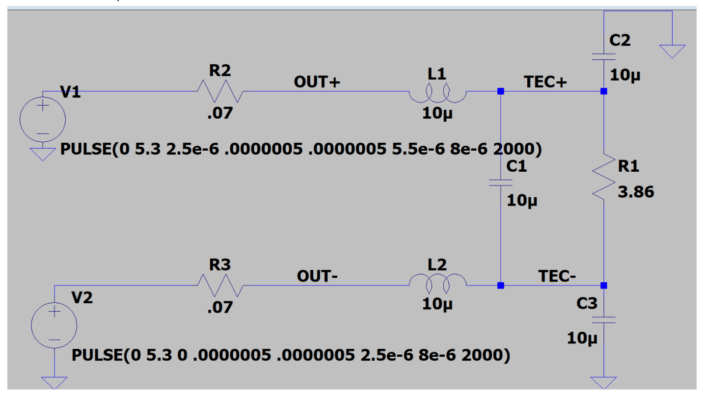
We're trying to use a DRV592 H-Bridge driver to drive a 2A TEC cooler for a laser diode, which we measure as a nominal 1.3 Ohm impedance.  We're also using the circuit shown on the datasheet front page and on the Eval board schematic for our output TEC low pass filter.  We're using 10uH wire-wound inductors on OUT+ and OUT- pins, followed by 10uF ceramic caps to complete the low-pass filter.  We also have a 5A Hall effect current monitoring chip on one of the TEC leads but that shouldn't be impacting the circuit performance.  The PVDD pins are supplied with a high current 5.5V supply which is the max rating on the datasheet.

We're driving IN+ & IN- with a 100MHz PWM pair from an ATMEL MEGA with varying duty cycle (5V).  SHUTDOWN and HIZ are driven constant High.

The problem we have is as soon as we power up the circuit, the FAULT0 and FAULT1 lines go to 0 (overcurrent), and the DRV592 seems to go into a loop where the 4A overcurrent protection sends the outputs Hi-Z, resets after 3us, tries to start again and repeats.

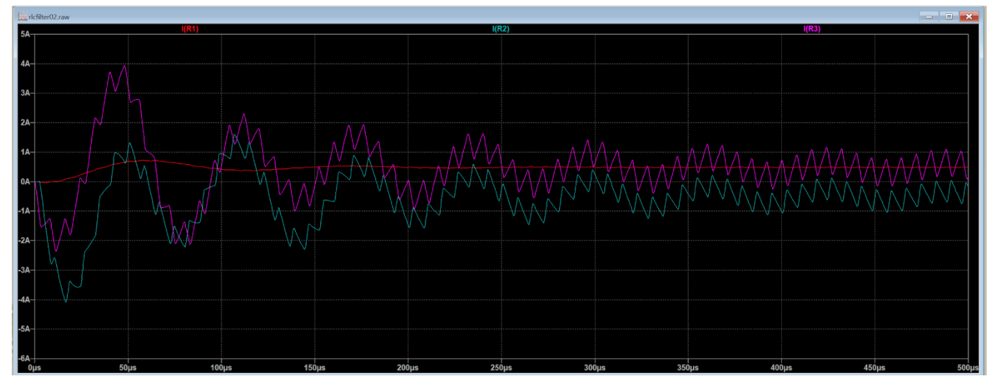
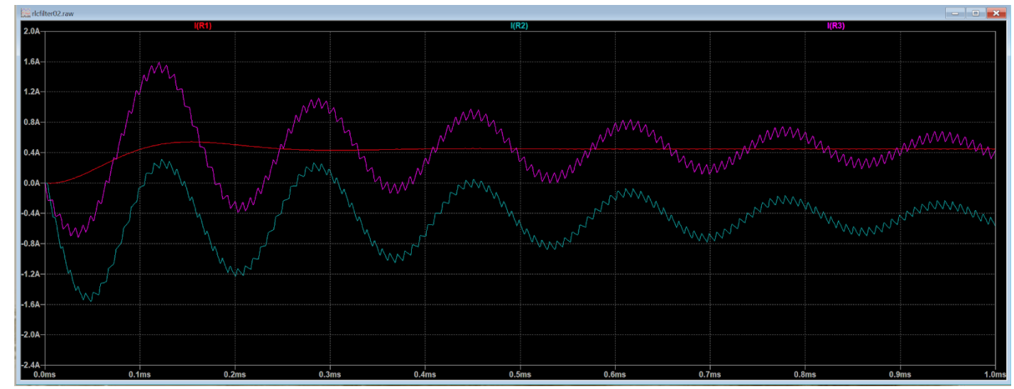
We can get it to run by increasing the load to 7 ohms or more.  We've tried changing the low-pass filter inductor and capacitor values to reduce the output current ringing which our LTSpice model tells us can exceed 4A with a 5.5V supply with the lower TEC impedance values.  But we haven't been able to get a low-pass filter combination to reliably start and maintain normal operation (FAULT 1,1).  It keeps tripping back into overcurrent mode and stays in that loop.  When it is working the TEC current draw never exceeds 1.7A even at DC.

We *can* get the circuit to work by reducing the PVDD supply to somewhere below 4V.  

We think the problem is the current ringing we're seeing at OUT+ or OUT- on transitions both on the scope and in LTSpice is tripping the 4A overcurrent limit and starting this protection loop.  I've searched all over for others having the same issue without any success.  We can replicate the issue on two separate boards so we don't think we have any board faults.

Our plan now is to add a separate variable step-down supply for PVDD so we can dial the supply voltage down to a level where we stay out of overcurrent mode.  This will probably work but limits how hard we can drive the TEC to below its 2A max rating, so we're losing some control margin for hot operating conditions.

Any suggestions how we can prevent this transient over-current protection fault using the max 5.5V as a supply?

Thanks 

  • Hi Dan,

    Wait you mean that you are inputting a 100kHz input signal not a 100MHz input signal right?

    One way to verify that it's truly ripple current that's causing the issue is by increasing the input switching frequency. With 100kHz, it's possible you are getting about 0.69A ripple current. Which, while high, shouldn't be enough to cause the issues you are seeing. However it's a good starting point to check.

    Would you also be able to take a screenshot of the input and output voltage and current waveforms?

    Best Regards,

    Robert Clifton

  • Hello Robert, Thank you for such a quick reply.

    Yes, our input PWM is running at 100kHz, which seems like plenty.  I don't have any real clear scope shots of the TEC outputs.  I lack a differential probe and triggering has been fussy due to the transition ringing.  However the peak ringing voltages I do capture are pretty consistent with the LTSpice model for the LPF I made.  We've tried two different TECs on this driver circuit,  The 1.8(ish) Ohm @A Diode package TEC and a nominal 12V 3.8 Ohm 2" square TEC which also exhibits the immediate 0,0 overcurrent on powerup using 5,5V.  Here is the LTSpice model for the LPF where R1 is the TEC load, and R2 and R3 represent the datasheet MOSFET resistance for the H-Bridge drivers, which the block diagram shows as the location where the internal over-current sensing takes place:

    PVDD is 5.5V, so the 100kHz square wave for V1 and V2 w 70/30% duty cycle is modelled at 5.3V for the internal drop:

    If we put the LTSpice current probe on R1 and R2, here is the current ringing we see at each transient at 5.3V :


      The initial current ring pulse at 20 and 50us just touch + and - 4Amps then flattens out to the steady-state ripple current.  Our working theory is that this initial ring pulse is tripping the internal 4A OC limit.  This causes V1 and V2 to go Hi-Z for 3-5us before trying again and we get another ring which trips the OC again and so on.  During this OC mode the two outputs move almost completely in phase and no significant current is supplied to the TEC as verified by an in-line ammeter.

    As I said, we can get this to work if we decrease PVDD to below 4V.  Another way we were able to get it working was to increase the two wire-wound inductors to 68uH.  This also significantly decreased the max steady-state TEC current we can supply and produces an LTSpice transient trace like this:


    The initial transient current is now just 1.6A max but the steady-state TEC supply current goes all the way down to 500mA.  With a 3.3V supply and 10uH we can get the current up to about 1.6A max.  Ideally we'd like to be able to supply the rated 2A TEC current for maximum cooling, but increasing the PVDD voltage trips the OC protection before we can hit that.

  • Well shoot, it looks like the .png screenshots I took didn't post on the forum.  Let me try inserting them.

  • Hi Dan,

    Do you also have C1 in your board layout? Could you remove it and see if it works?

    I'll continue to think of other possible reasons this could be happening.

    Thanks,

    Robert Clifton