This thread has been locked.

If you have a related question, please click the "Ask a related question" button in the top right corner. The newly created question will be automatically linked to this question.

PCM1840: Problems with lock of TDM4 data stream / PLL

Part Number: PCM1840

Hello,

We have implemented the PCM1840 ADC in several new and reworked designs. In only one case we are having heavy problems to get the converter running stable.

The problem we have:

After switching on the device and booting the DSP, there is either a "broken looking" data stream or just a zero out of the ADCs. All clocks are running and looking fine.

Now if I just "short" the LRCLK to ground, to skip it out for a moment and then release it, the converter starts working normal. Also if the converter is running normal and I set it to PDN, sometimes it comes up again and sometimes not. So my guess is, it might have something to do with the PLL of the converter?!

Both of the converter are acting similar and we even already replaced the parts with new ones.

The configuration:

2xPCM1840 running in TDM4 left-justified mode as slave hooked up to a ADAU1452 - one data line per converter to the DSP and a common BCLK and LRCLK from the DSP to the converters.

BCLK is running at 6.144MHz pos. Edge

LRCLK is running at 48kHz pos. Egde (right now we are running pulse mode, but also tried 50/50)

FMT1, FMT0, MSZ, MD0 are set to low

MD1 is switchable for DRE application.

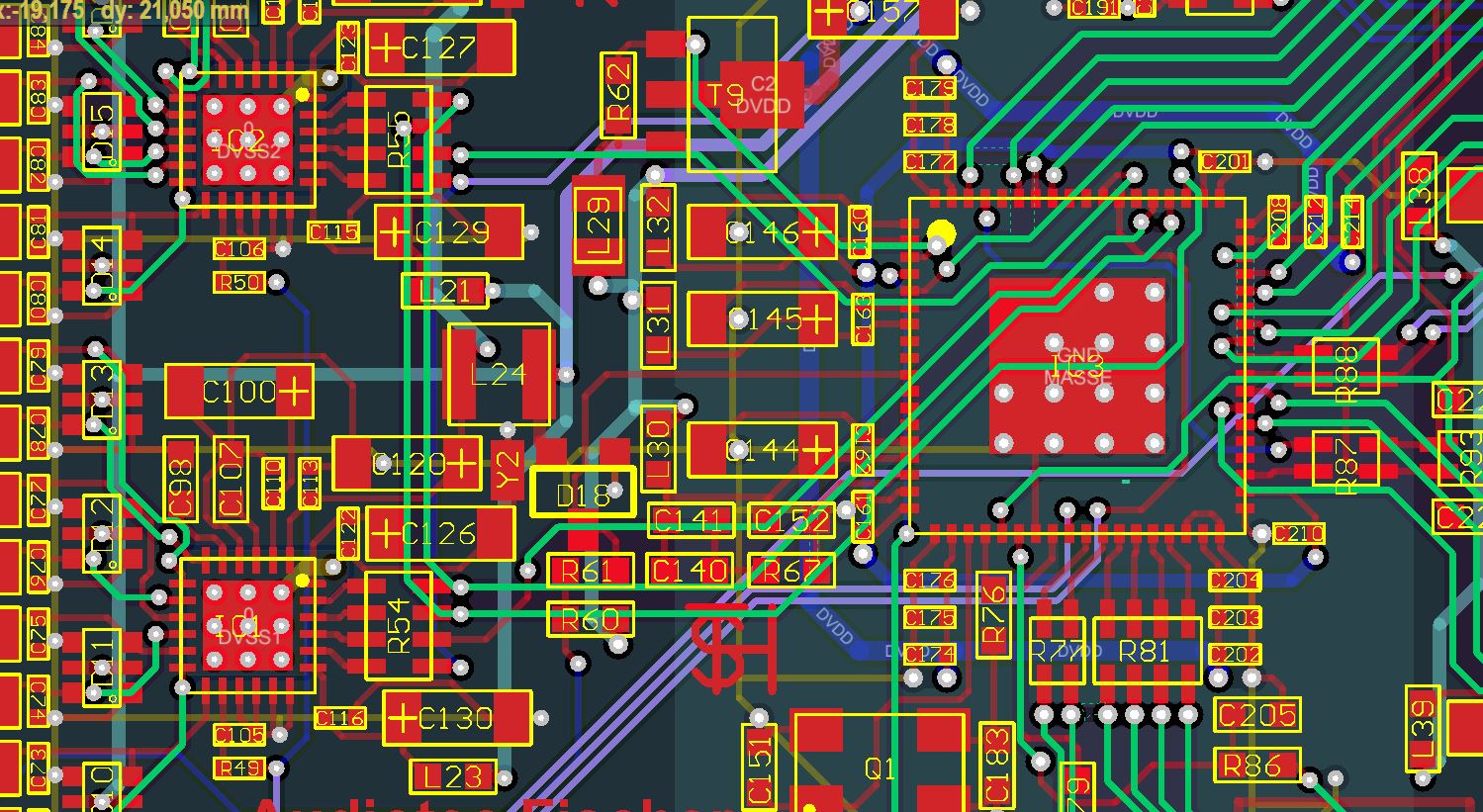
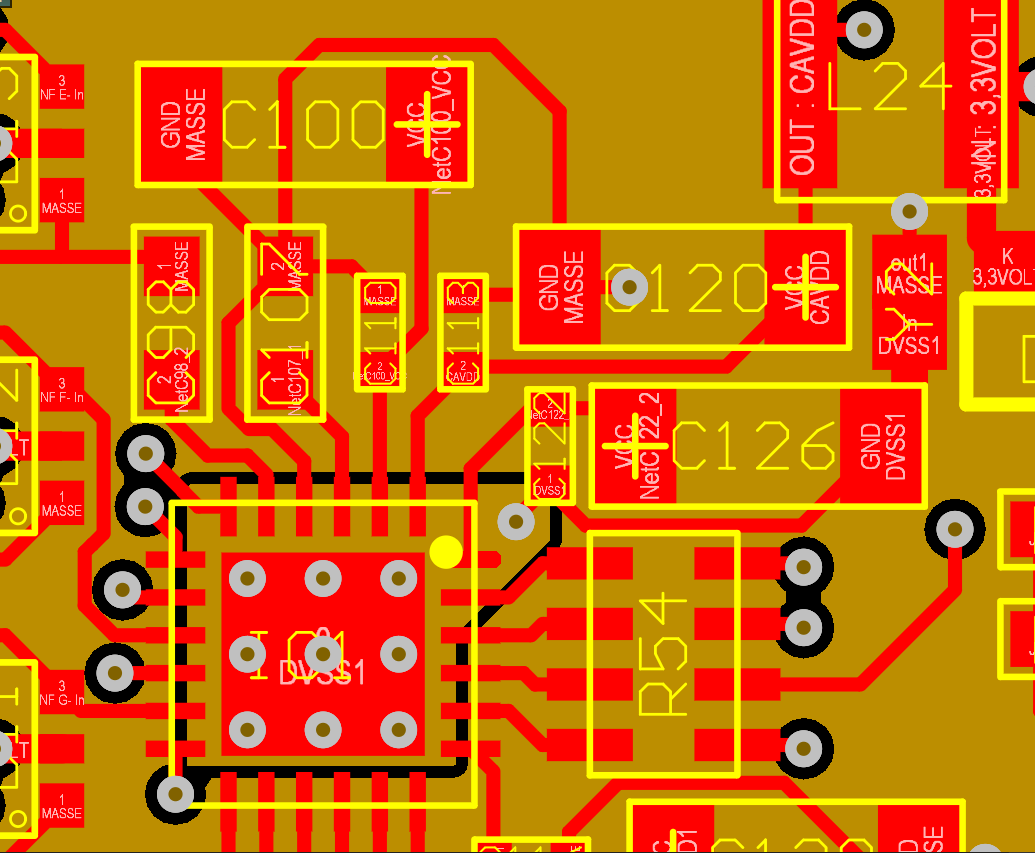
The local layout and the power supply of the ADCs is similar to our running implementations of the device, if there are some critical points in layout and power, I can point out more details on this.

Did someone have a similar problem to this or an idea how to proceed the debugging?

Thanks for your help,

Florian

  • Hi Florian,

    Welcome to our e2e forum!  I'm sorry to hear that you are having issues with the PCM1840!  From the description above, it sounds like you are doing everything right.  My initial thought was that you might have an issue with the clock - over/under shoot, reflections, ringing, etc.  Do things happen to work better when you are probing the BCLK and/or FSYNC?  If you could pass over your layout, we'd be happy to take a look.

  •  Hi Tom,

    I am the colegue of Florian and here you find a screenshot of the layout showing the section with the two PCM1840 and the ADAU1452.
    We are using a 6-layer pcb and all high-speed data lines are located in an inner layer (here the "green" layer). For better visuality the screenshot does not show the filled areas which are connected to ground.

    As Florian already mentioned this is the only project where we are facing such problems. Other devices with similar design/configuration did work properly right from the beginning.


    Regards,
    Robin 

  • Hi Robin!

    Thanks for the screen capture!  Was there a second screen shot that you meant to attach?  If so, it did not come through.  From the layout side, everthing seems correct as well - I don't immediately see any issues.  The two devices seem to follow the same basic pattern and I see that AVSS ties back to AGND @ C120 on IC1.  Is that a solid ground plane on the yellow layer or are all the grounds stiched together somehow?

    Funny thing - I can see the TSH, I used to add my initials to boards in a similar way TEH blends together nicely...

  • Hi Tom,

    no - there was no second screenshot. The yellow layer is a solid ground plane and we are using the fills of other layers as additional ground. All are properly connected by "tons" of vias.

    Regards,
    Robin

  • Hi Tom,

    no - there was no second screenshot. The yellow layer is a solid ground plane and we are using the fills of other layers as additional ground. All are properly connected by "tons" of vias.
    I have added a more detailed scrrenshot of the ground connection of the PCM1840.

    Regards,
    Robin

  • Hi Robin,

    Thanks for confirming the layout.  Can you send over screen shots of the clock and data?

  • Hi Tom,

    unfortunately I do not have any screenshots of the clock signals available at the moment, but of course we already paid attention to this.
    Actually the wave forms of FYSNC and bit clock were almost perfect with sharp slope and negligible overshoot.
    So we are convinced that the clocks will not cause the problem.

    Regards,
    Robin

  • Hi Robin,

    Actually I was hoping you could provide a screen shot of the 'broken data', along with the BCLK for reference.

  • Hi Tom,

    thanks for your help so far!

    I made some screen shots of the clock- and data lines.

    This one shows a close up of the rising edge of LR&BCLK in "fail mode" purple is DATA OUT from the ADC:

    This is the same after "shorting the clock" running normal:

    This is 1FS of the fail state, again purple = DATA OUT:

    Same for running normal:

    Here a close up of LR/BCK

    Hope this helps!

    Thanks,

    Florian

  • Hi Florian!

    Thank you for the screen shots!  Just to be sure that I understand correctly, in 'fail' mode, it looks like the SDOUT is stuck - repeating a pattern that is not valid data.  Is that right, like the "1FS of the fail state" above - that output pattern continuously repeats? 

  • Hi Tom,

    The pattern is not 100% stuck, but some kind of similar over a period if time.

  • Hi Florian and Robin,

    Thank you for the feedback!  At this point, me and the rest of the team are still a little stumped here.  The clock and data lines look pretty clean to me, so I'm less likely to point there.  The BCLK frequency in the plots you sent over change a little, but that might just be your scope.  What are the differences between this project and the others that have no issue with the PCM1840?  Layout the same, but different software?

  • Hi Tom,

    The software of the board controller is part of our framework, so the sequence is the same as in our other products. The DSP software of course is slightly different, but the configuration of the clocks and interfaces in the ADAU1452 is a fixed part of the boot process.

    As you can see in the scope shots, they should be running in the right modes (even if we would have messed up our processing - the DATA OUT of the PCM1840 should work). To be sure, I recompiled the DSP file with the latest version of the Sigma-DSP tool just yesterday.

    I had the board laying around in 'fail mode' for maybe two hours and at some point it just started to work, but as I said after minutes to hours.

  • Thank you Florian,

    So one concern that has come up is with your grounding.  The PCM1840 is on it's own little ground 'island' which is fine, but I want to confirm that it's just that one somewhat thin trace up through C107, C100 and around to C120 to a via that gets AVSS back to your ground plane.  How is AVSS connected on the designs that you are not experiencing issues with?

  • Hi Tom,

    in all designs the AVSS in the same way. We have made tests with a mor solid connection of the ground plane, but this does not make any difference at all.

    Regards,
    Robin

  • Hi Robin,

    You have us scratching our heads on this one.  Both parts on the board behave the same way?

  • Yes - both behave exactly the same way. It's weird.

  • Hi Robin,

    Just a thought, but have you tried configuring one of the devices as a Master?  Jitter in BCLK should not cause the issue unless it causes any timing violation and in-correct BCLK cycles in one frame.  We actually look for the number of BCLK cycles in one frame and accordingly auto-configure the PLL however if some reason there is some timing violation in BCLK count then that can cause the clock error or device misbehavior.

    Since you are seeing issue for both devices and all boards tested so far, we're thinking there must be some external trigger/sensitivity either due to clock or board layout or some other ground bouncing etc which might explain the device or PLL behavior that you see.

    Are you by chance giving clocks to the device as free-running clocks (even during supply ramp-up) ? If yes, then can they try to give clocks (BCLK and FSYNC) after supply ramp-up is fully completed.