This thread has been locked.

If you have a related question, please click the "Ask a related question" button in the top right corner. The newly created question will be automatically linked to this question.

TPA2012D2: TLV320AIC3106 + TPA2012D2 : unwanted noise coming from the Amp

Part Number: TPA2012D2
Other Parts Discussed in Thread: TLV320AIC3106

Hello,

We have an audio configuration where we use TLV320AIC3106 as the Audio Codec, which is driving the TPA2012D2 Class D amplifier.

We are routing the MONO_LOP/M differential lines to the left input of the TPA2012D2.

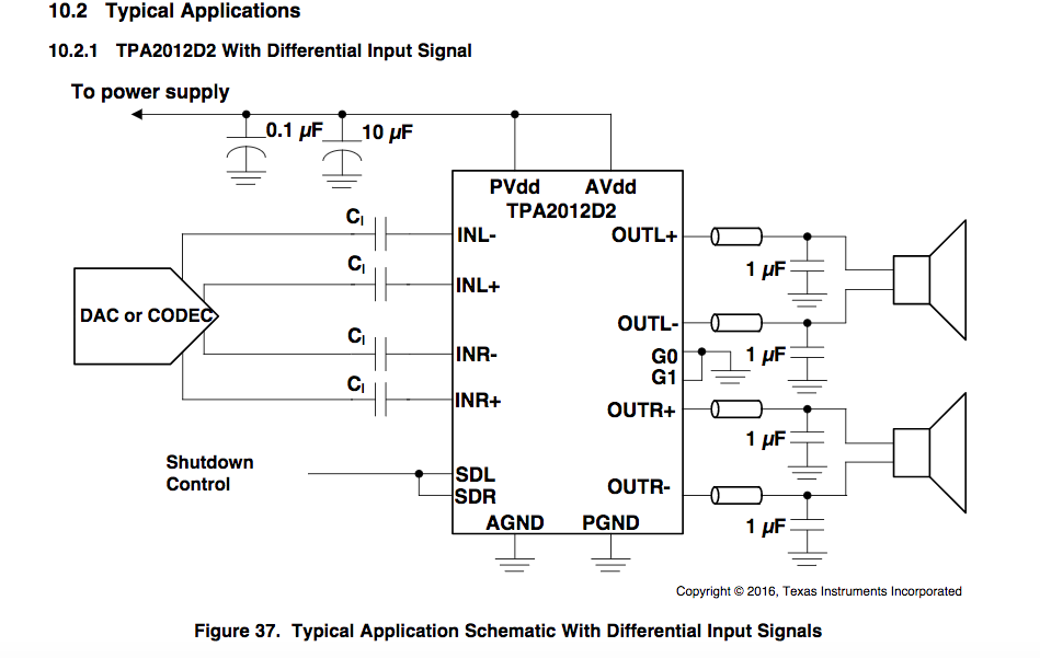
You will find below the schematic part of the design.

This design was made according to information coming from both tpa2012d2 spec and tlv320aic3106 spec.

1) The differential output of the TLV320AIC3106 drives the amp through 0.1uF serial caps (input capacitors), as suggested in the TPA2012D2 spec, section "10.2.1TPA2012D2 With Differential Input Signal"

2) The thing is, the TLV320AIC3106 suggests another circuit, as shown below (taken from TLV320AIC3106 spec) with serial resistors and a 4.7nF cap between differential lines

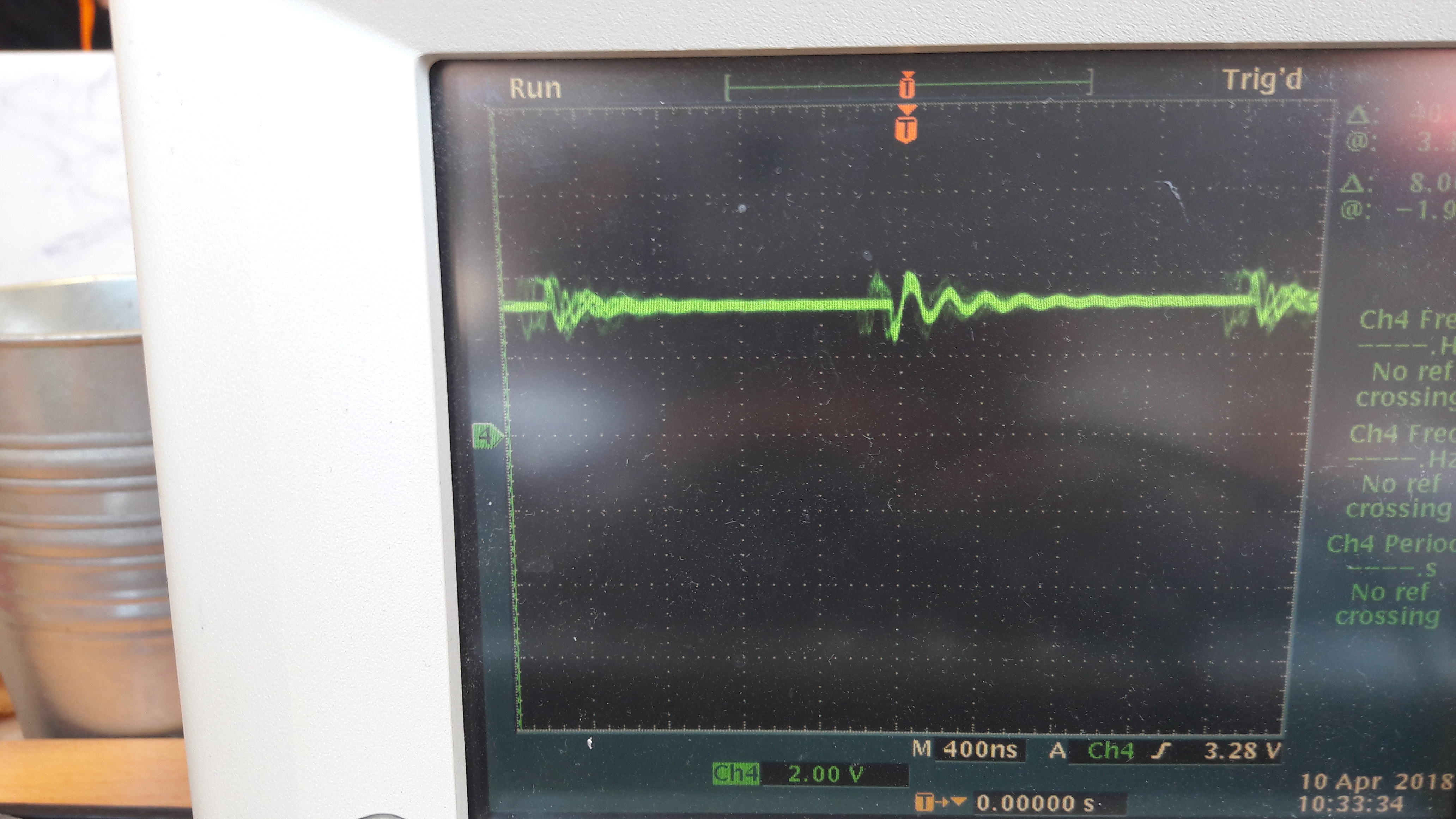
3) We measure following "noise" on the audio lines:

Which is then foud on our codec power supply: this is our analog 3.3V supply:

Could you please help us solve this "issue" ? How should we connect our codec and amp ? Through serial resistors and a 4.nF cap and input capacitors ?

Thanks for your help

  • Hi Yann,

    give this filter a try:

    And have you handled the two grounds TLV320AIC3106 with care?

    Kai

  • Hi Kai, we will try.

    Meanwhile we removed the serial caps on the differential lines, so the codec and amplifier are "disconnected". But we still see the noise on the supply.

    For TLV320AIC3106 we have three supplies: 1.8V digital, 3.3V digital and 3.3V analog which is derived from the 3.3V with ferrite bead.

    We also have a digital ground and an analog ground, derived from digital with ferrite bead.

    For TPDA2012D2 we are using the same 3.3V analog voltage as TLV320AIC3106 for AVDD, and same 3.3V digital for PVDD. Is that an issue ?

    Thanks,

    Please check our schematics below:

    Supplies shcematics:

  • Hi Yann,

    This seems to be decoupling problem. TPA2012D2 requires adequate power supply decoupling to ensure a high-efficiency operation with low total harmonic distortion (THD+N). Place a low ESR ceramic capacitors, 10uF and 0.1uF capacitors should be placed within 2mm of the PVDD/AVDD. The decoupling capacitors of TLV320AIC3106 should be placed as close as possible to the device.
    Make sure that the decoupling capacitors are placed correctly.

    Best Regards
    José Luis Figueroa
    Audio Applications Engineer
  • Hi Yann,

    having the inputs disconnected is no good idea, because the inputs need to see the low ohmic output impedance of driver. Otherwise the inputs act as an antenna and noise can easily be injected into the inputs.

    The filtering I recommended you is explained in section 9.3.3 of datasheet of TPA2012. It's important to shunt the high frequency noise from the switchings directly to GND. This can only be accomplihsed by caps referenced to GND.

    I see in your schematic, that you have a ferrite bead between DGND and AGND_AUD? Why do you have a ferrite bead mounted there?

    Kai
  • Hi All,

    We have the decaps in pace for TPA2012. Please check extract of our placement below.

    The IN_R indeed is not grounded. We will give a try.

    Kai, the 9.3.3 section is for single ended configuration. We are using differential configuration. For differential configuration according to TPA2012 spec, only serial input caps are needed.

    According to TLV320AIC3106 spec (see typical application section), we also need to place 560 ohm serial resistors and a 4.7nF cap between dfifferential lines.

    However, as explained, we believe the noise is coming either from the supplies or the ground. This is because we are still seeing the noise even when the differential lines between TLV320AIC3106 and TPA2012D2 are cut. And the only way to make the noise disappear is by shutting down the amplifier (both SD signals driven to low).

    We indeed placed a ferrite between the 2 ground planes to filter even more high frequencies ... We believe It is recommended sometimes.

    You did not answer my questions :) : can we share the Analog ground between tpa2012D2 and tlv320ai3106 ? and can we share the Analog VDD between tpa2012d2 and tlv320ai3106 ?

    We have a tpa2012d2 eval board here so we are going to "play" with it. At first glance we are not seeing the noise. We will try adding more caps .. Or maybe you can see an outstanding issue on our route/ placement  design ?

    Thanks,

  • Hi Yann,

    you wrote:

    "Kai, the 9.3.3 section is for single ended configuration. We are using differential configuration. For differential configuration according to TPA2012 spec, only serial input caps are needed."

    Yes, I know. Nevertheless I would give the filtering caps to GND a try. Have again a look at my schematic. It's designed for differential configuration. This sort of filtering can be very helpful in noise contaminated systems.

    You wrote:

    "You did not answer my questions :)"

    Dear Yann, I'm not an employee of TI. I'm only here for fun...

    The proper design of grounds is crucial when working with mixed analog digital systems. It's important to keep the analog and digital wiring separated as much as possible. The analog signals must only run over analog ground planes and the digital signals must only run over digital ground planes. You can take a digital supply for analog purposes, but you must introduce a filter which prevents the digital ground return currents from flowing over analog ground connections. How this can be realized depends on actual application. There are no general rules. But you will need lots of ferrite beads in the supply lines. In mixed analog digital systems I often use pi-filters for the power supply decoupling at each chip, even for the digital chips. This makes that the high frequency decoupling currents from the chips are trapped in the pi-filter and no ground return currents can flow allong the ground connections of the whole PCB.

    If the only connection between your grounds is via a ferrite bead, then you have probably made a mistake.

    Sorry, I cannot suggest more without knowing more about the whole circuit and the PCB's layout. Also, my time as amateur here is very limited... :-)

    Kai
  • Hi Kai,
    Apologies, I did not mean to be rude. Thank you very much for sharing your knowledge, I really appreciate.
    Indeed the issue was related to the ferrite. Now everything's working fine.
    I thought you were TI, hence my comments on the app note / spec .
    Anyway, thanks to you this is now working ! So THANK you !
    Best