This thread has been locked.

If you have a related question, please click the "Ask a related question" button in the top right corner. The newly created question will be automatically linked to this question.

PCM5102A: Group Delay

Part Number: PCM5102A
Other Parts Discussed in Thread: PCM5102EVM-U, PCM9211EVM-U

Hi,

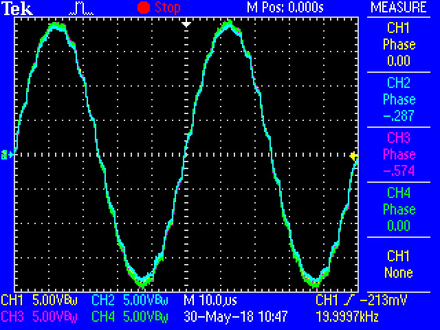
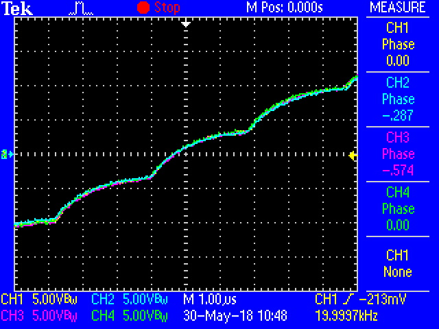
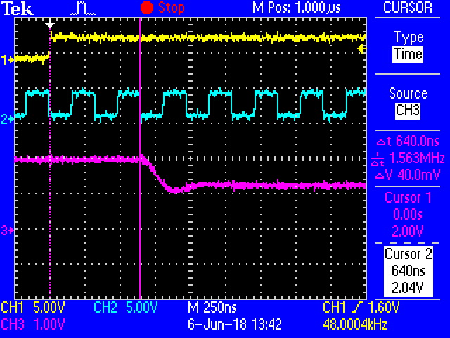
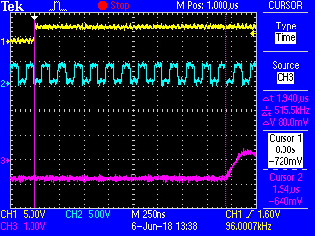
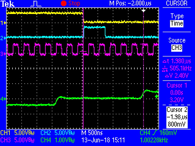
A customer pointed out PCM5102A has a drift of Group Delay.
He tested using two PCM5102A, he inputted same 20 kHz sine wave signal data and clocks to them.

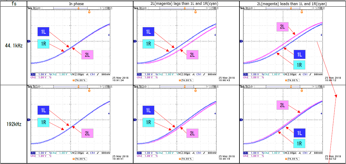
1L: PCM5102A-1 Left channel Output (blue)
1R: PCM5102A-1 right channel Output (cyan)
2L: PCM5102A-2 Left channel Output (magenta)

His questions are the reason why Group Delay drifts and whether the other DACs also drift.
In reference to this question, x8 Normal oversampling digital filter latency is 20ts as Typical Performance, in page 4 of datasheet.
However, in Table 4 Normal x8 Interpolation Filter of page 17, Filter group delay is 22ts. Which value is correct?


Best regards,

Akio Ito

  • Hi Akio,

    Thank you for your query. The engineer responsible for this part is not available due to holidays. He will get back to you soon.

    Regards,
    Uttam Sahu
    Applications Engineer, Precision DACs
  • Hello Ito-san,

    Is this just drift over time or is there also some temperature change included in this capture (either external influences to temperature or board-level self-heating over time)?

    I will need to check in on the group delay differences in the document.
  • Kevin-san,

    Thank you for your reply.
    I also tested whether the group delay of PCM5102A drifted, using two PCM5102EVM-U boards. I could not find the drift at all, and 4 channel outputs were completely in phase.

    The difference between our customer's measurement waveform and mine is including or not including x8 interpolation frequency signal. His LPF frequency response may be very sharp. Generally, a sharp LPF has a peak of group delay around cut-off frequency. So, I will suggest to him test again without his LPF.

    I have measured PCM5102A group delay using square wave I2S signals. The specification of square wave is as follows.

    Sample rate: 44100 Hz
    Data depth: 16 bits
    Signal: 689 Hz, 0dBFS square wave
    (toggled 7FFFh/8001h per 32 sample periods)
    Phase: Reverse phase between L/R channel

    I2S Left channel data is valid after the next LRCK falling edge, Right channel data is valid after the next LRCK rising edge. I think that the starting point of group delay measurement should be the rising edge of 1.5 LRCK clocks after from DIN bit pattern changed.

    CH1: DIN (yellow)
    CH3: LRCK (magenta)
    CH2: OUTL (cyan)

    My measurement of PCM5102A total group delay including x8 interpolation filter delay was 21/fs.

    Best regards,

    Akio Ito

  • Ito-san,

    Changing the filter settings on your customer's board may be a decent experiment to isolate differences between your setup and theirs.

    However, I am a bit concerned that the issue could actually be in their HW since they are (presumably) using their own hardware. In that case the layout for the two devices will be different, while in your setup the two EVM boards are identical. There could be some PCB level or even SCH level differences between the two units which are contributing to difference phase responses. Potentially also different loading conditions for the two channels could be creating this.

    So, I would encourage that we also look into hardware level differences in the SCH and PCB.
  • Ito-san,

    This is very nice data! Please let me know the customer's response.
  • Duke-san, and Paul-san,

    Thank you for your replies. Our customer sent us measurement wave form shown below today.

    According to his note under the wave form, the phase between both devices does not fluctuate during DAC operation. DACs seem to start operating with one of upper three types phase wave form.
    I requested to him the information of SCK/LRCK/BCK settings. And I suggested tune the dumping resistors of these clocks.

    Best regards,

    Akio Ito

  • Hi Ito-san,

    I think the SCK/LRCK/BCK information would be useful.

    Thanks!
    Paul
  • Paul-san,

    Thank you for your reply. The clock settings informed from our customer are as follows.

    Left Justified.
    64BCK.
    fs=44.1k/48kHz(Normal), 88.2k/96kHz(Dual) 176.4k/192kHz(Quad).
    4-wire: MCLK=256fs(Normal/Dual), 128fs(Quad).

    He sent to us the clock wave form shown below, too. I understand that he does not need to tune the dumping resistors value. 

    I did repeat experiments with his clock settings by AudioPrecision COAX output, PCM9211EVM-U DIR to 4-wire serial output and PCM5102EVM-U. When the fs is not changed after power on, DAC output step timing to LRCK seems to be always same position as shown below. But if once the fs is changed, DAC output step timing to LRCK is not same position.


    CH1: LRCK (Yellow)
    CH2: BCK (Cyan)
    CH3: OUTL (Magenta)


    Best regards,

    Akio Ito

  • Hi Ito-san,

    That is interesting data. I will bring it up with our design team for an explanation, but I suspect it is complicated from a digital design standpoint.

    For my clarification, is your customer concerned that this is a problem?

    In addition, if the XSMT is asserted during the sample rate change, does the edge reset?

    Thanks!
    Paul
  • Paul-san,

    Our customer uses five PCM5102A per one product. He is now checking the phase between two PCM5102A. Of course, he hopes not only two but all five PCM5102A be in phase.
    If TI can explain that the difference between minimum and maximum of the delay does not exceed 1/(44.1kHz*8), I think there may be room for them to permit it. Because the time of 1/(44.1kHz*8) is only 1-mm in terms of wavelength.

    velocity of sound: 340 m/sec
    1/(44.1kHz×8) =1/352.8 msec

    Our customer explains that the DSP of their product outputs clocks of fs=48kHz at power on, then the fs is changed to the last fs at previous power down via 44.1kHz. And the fs is changed via clock stopping period and unstable clock period to the target fs.
    I don't know whether their product controls XSMT terminal at the fs change timing.

    Best regards,

    Akio Ito

  • Paul-san,

    I did repeat experiments with our customer's clock settings again by playing a ±1/2FS square wave wav file.
    Playing only the fs=44.1kHz wav file repeatedly, I found four cases of output delay time, 5-1/2, 6-3/4, 9-1/2, 10-3/4 BCK as shown below.

    CH1 (Yellow):     LRCK   44.1 kHz
    CH2 (Cyan):       DIN      C0010000h / 3FFF0000h 
    CH3 (Magenta): BCK     64fs, 2.8224 MHz (Magenta)
    CH4 (Green):     OUTL   w/o LPF


    Best regards,

    Akio Ito

  • Paul-san,

    I did repeat experiments again, today too.

    I got 44.1k, 48k, 96k and 192k fs datum respectively with delay dispersion of 7.5 BCLK equivalence, as shown below.

    May I regard the dispersion of output delay as within 8 BCLK clocks when Serial Audio Data is 64 BCLK per sample ?

    Best regards,

    Akio Ito

  • Hi Ito-san,

    I just wanted to loop back with you on this. I think the difference in the devices is likely due to some delays at power on and initialization. These devices are fairly complicated with multiple inter-connected clocks and state machines. I suspect that at POR some devices power earlier than others, likely due to differences in "power-good" thresholds in the supplies and XSMT circuitry. This may mean that certain internal state-machines may be different in the different devices. I do not expect this to ever be greater than a few BCK cycles, as you have scene.

    Thanks!
    Paul
  • Paul-san,

    I visited the customer last week to explain this problem. The summary of my explanation to the customer are as follows.

    1. Group Delay of PCM5102A is almost decided by the interpolation filter. I guess the group delay is at least 19/fs from frequency response of the Normal x8 interpolation filter. Sorry, I cannot show the details of the calculation here.

    2. LRCK and DIN have specifications of setup/hold time to BCK. Therefor, the serial data on DIN is converted into parallel data by BCK.
    On the other hand, the delta-sigma modulator works by the clock sourced from SCK frequency divider. The interpolation filter also may work by same clock source. These clocks are asynchronous to BCK, because BCK has not any setup/hold time spec to SCK.

    3. The interpolation filter clock should be synchronized with BCK to get the parallel input data. At this time, up to 7.5/(64×fs) dispersion of the delay may occur.

    The customer agreed with my these explanation. Thank you for your cooperation.


    Best regards,

    Akio Ito