A related question is a question created from another question. When the related question is created, it will be automatically linked to the original question.
If you have a related question, please click the "Ask a related question" button in the top right corner. The newly created question will be automatically linked to this question.
When changing FS, I recommend muting the device through the XSMT pin. The auto-mute cannot be disabled in the PCM5100. In the past we have recommended that the customer add a 1LSB offset to their I2S data in their onboard processing. This means that when there is no I2S data, the bus is transmitting '1's.
Hi Paul,
If we add 1LSB offset, the output SNR will become worst, right?
Can we add a inverter before DIN(pin 14) to make sure that all bits are non-zero when auto mute? Do you think that it works? Will it bring any side effects?
Adding a constant offset code will not change the SNR performance. Adding an inverter to the DIN signal is a way to do this (though all data will be inverted as well).
Hi Paul This is Gabriel Xu from South China OEM team. My customer encounter pop noise during using PCM5100A too and need your help.
My customer is using PCM5100A+TPA3138 total solution. Pop noise issue reported during system power up.
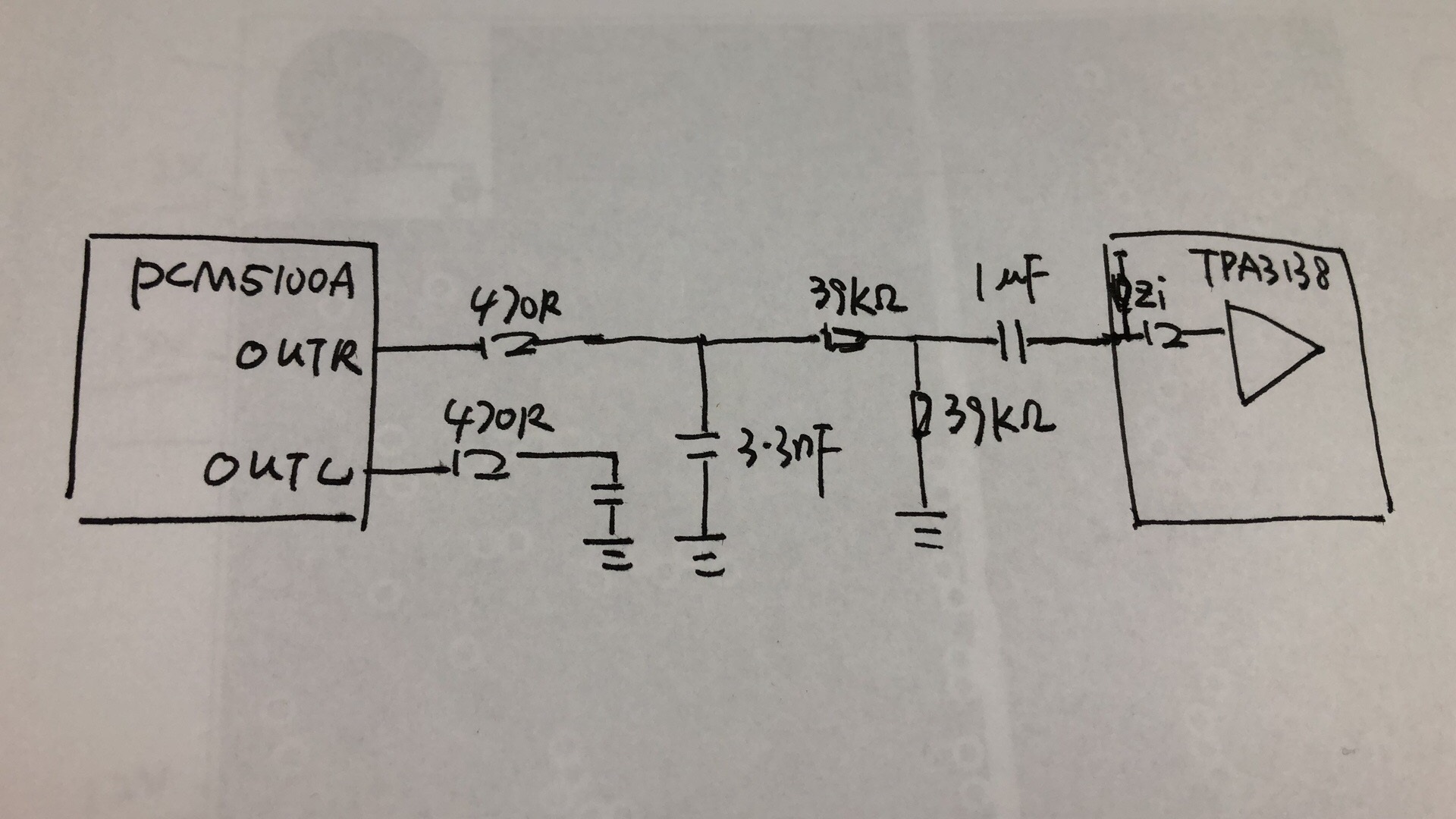
The schematic is shown in diagram2. Customer added a pair of resistors divider to adjust the output gain of the ADC is shown as diagram1.
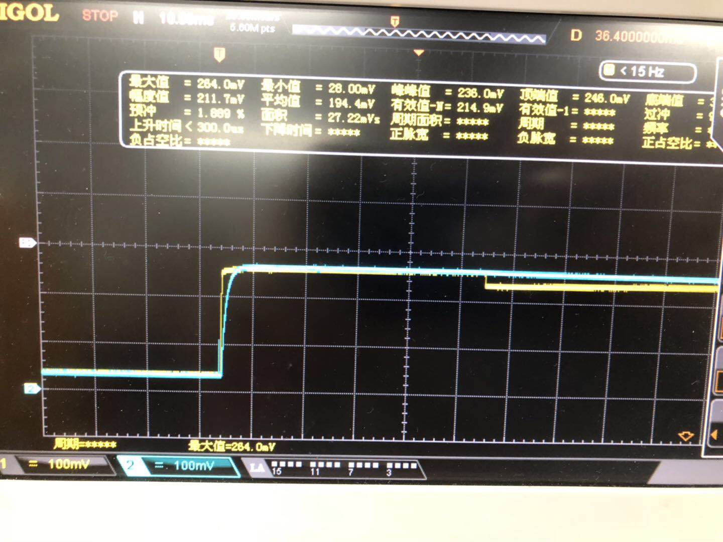
I have measured the IN+ and IN- waveform of TPA3138 during power up and the waveform is shown as diagram3.
The yellow waveform in diagram two is RINP voltage that is output from DAC.
It seems RINP voltage ramp up faster than RINN but will have a drop in 50ms. As the amplifier will start switching after mute pin release 50ms. So it should be the RINP voltage drop lead to the pop noise not the first voltage gap cause the pop noise.
Hi Paul
I also want to know if the 0dBFS input signal will still make output clipping even with lowest amplifier gain.
Do we have other methods to adjust the gain besides to reduce the input signal?
Could we add resistors divider in DAC output to reduce the output level?
What should we notice if we do so?
Thanks in advance.
The pop that you are seeing is due the PCM510xA calibrating its output to remove it's DC offset. This is a static function on the PCM510xA can cannot be prevented. In general, I recommend that the TPA be muted until the PCM's output is settled. From your description, it seems like the customer has this capability, but the amp is un-muted too soon.
Per your second question, this event is caused by the offset calibration, not clipping.
TPA3138 didn't have independent mute function pin. It only have SD(shut down) pin.
TPA3138 input terminal will stay in HIZ states until the SD is release.
After the SD is pull to high, TPA3138 will wait 50ms before the H bridge start switching. So it mean that TPA3138 could immune DC offer set between differential input terminal for 50ms.
About the calibrating function I didn't found any description about that. Could you give me some explain how it work and how it influence amplifier?
I understood the clipping issue have not relationship with the pop noise. I just want to ask another question how to shrink the DAC output voltage level besides to reduce the input signal level? Could we add resistor divider in DAC output? (The diagram shown in previous post)
The PCM510x is considered a DirectPath device, meaning that the output should be ground centered. Due to some offsets in the device, we calibrate output to reduce the offset as much as possible, so that it is closer to true GND. So the pop you are seeing is the device trying to remove the few millivolt offset. When the device goes into a hardware mute (auto-mute) the calibration is removed to save power.
Can the TPA be kept in SD until the PCM5100A output is established?
In addition, the output can be attenuated with a resistor divider as you describe. Just note that the total resistance cannot be less than the minimum load impedance specification, 1kOhm.
The pop behavior is due to the internal offset calibration to achieve a 0V common mode on the output. This offset is provided by enabling a static number of current segments in the delta sigma architecture. The downside of this is that if they device is in a low power state or the clocks are not provided, the device cannot keep those current segments enabled. The potential pops can occur at the following events:
1. After POR and valid clocks are applied the offset will be calibrated.
2. If zero-data is applied, the auto mute will enable approximately 20ms later, the offset calibration will be disabled.
3. Once non zero-data is applied during mute, the output will re-enable the offset calibration.
4. A clock error occurs, resulting in the offset calibration being disabled. Clock errors can be caused by the I2S lines being disabled, or invalid clock rations being present.
Conditions 1 and 4 are unavoidable (unless they can guarantee no clock errors). Conditions 2 and 3 can be prevented in two ways:
1. Disabling the auto-mute – this is only available on I2C/SPI controlled devices, like the PCM5122/42.
2. Preventing zero-data – this can be done by adding a 1LSB offset to the data in the DSP, or by adding a digital inverter to the DIN pin.
For condition 1, the offset calibration occurs within 20ms of the I2S data being provided to the device.
Hi Paul
Thanks for your reply and its very clear!
I have confirmed with MPAA BU TPA3138 H-Bridge will start switching after 50ms delay from device enable.
So it should be immune input mismatch pop noise for 50ms. So ADC offset calibration within 20ms should be fine for TPA3138.
We have located the root cause is the large value DAC output resistor divider. (39Kohm)
The large input resistance will enhance input offset mismatch of the TPA3138.
We fixed this issue after we modified this resistor to 1kohm.