Other Parts Discussed in Thread: OPA1622,
Hi,
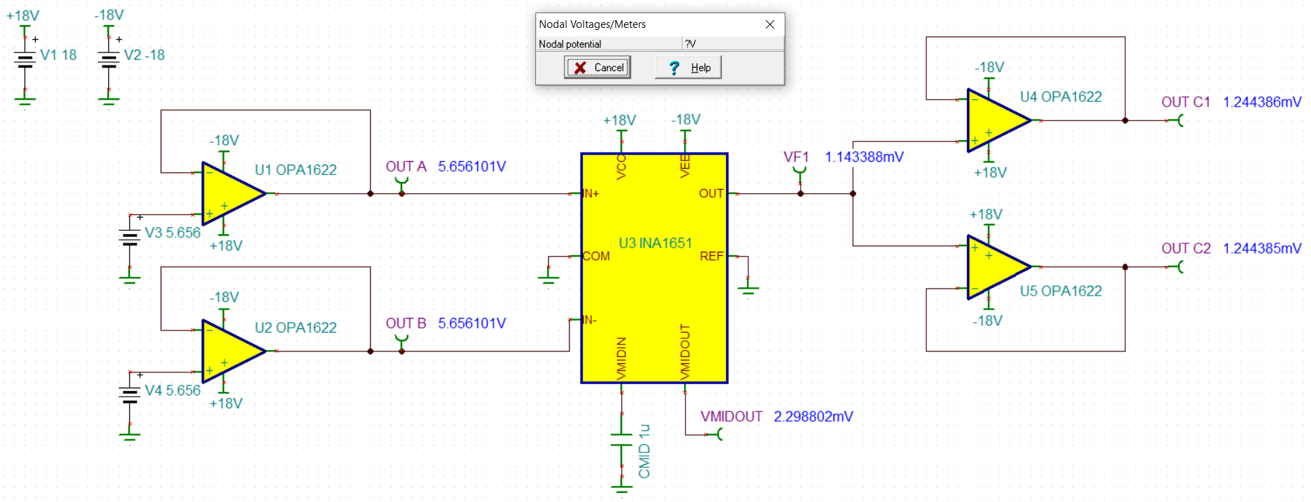
For a measurement project I am trying to subtract headphone output channels of a soundcard. My output buffers are OPA1622, one half for each channel.
OPA1622 outputs is connected to IN+ and IN- of INA1651. I have dual supply, REF connected to ground. Also COM is to ground. I have no coupling capacitors on INA1651 inputs. The internal reference generator is left unconnected.
INA output is fed to paralleled OPA1622.
OUT C DC voltage with no input signal is 7mV, good.
Connecting OUT A, OUT B, OUT C to 4ch scope reveals this problem:
OUT A - OK, same phase, same level 2Vrms
OUT B - OK, same phase, same level 2Vrms
OUT C = 2 x (OUT A) - 1 x (OUT B), i.e. 2Vrms
Please note that the IN+ is amplified x2.
For channel B zero (i.e. only OUT A 2Vrms) OUT C is 4Vrms
For channel A zero, (i.e. only OUT B 2Vrms) OUT C is 2Vrms, with opposite phase to channel B.
Since my signal is a 24bit soundcard, if I generate the channel A at half the level of channel B (exactly 0.500), OUT C is zero down to millivolts. This precision suggests it must be something with precise resistors - these are only in INA1651.
All the signals look very clean on the scope, no spectrum analysis was done though (that was to be the next step...).
INA1651 purchased directly from TI.com, brand new.
Please excuse the crude hand drawing.
Thanks a lot in advance for any suggestion, what could be wrong. Since all the chips are added inside into an existing soundcard, the pins are hard to reach.