This thread has been locked.

If you have a related question, please click the "Ask a related question" button in the top right corner. The newly created question will be automatically linked to this question.

TLV320AIC3100: High mic ADC values after reset or power up

Part Number: TLV320AIC3100
Other Parts Discussed in Thread: CC2640R2F

Hi,

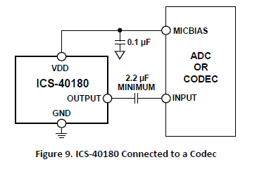
I'm having a problem with our hardware using a TLV320AIC3100 that I don't seem to be able to solve. We are using two TDK ICS-40180 mics at the RP and LP inputs and power them using the codec's MICBIAS.

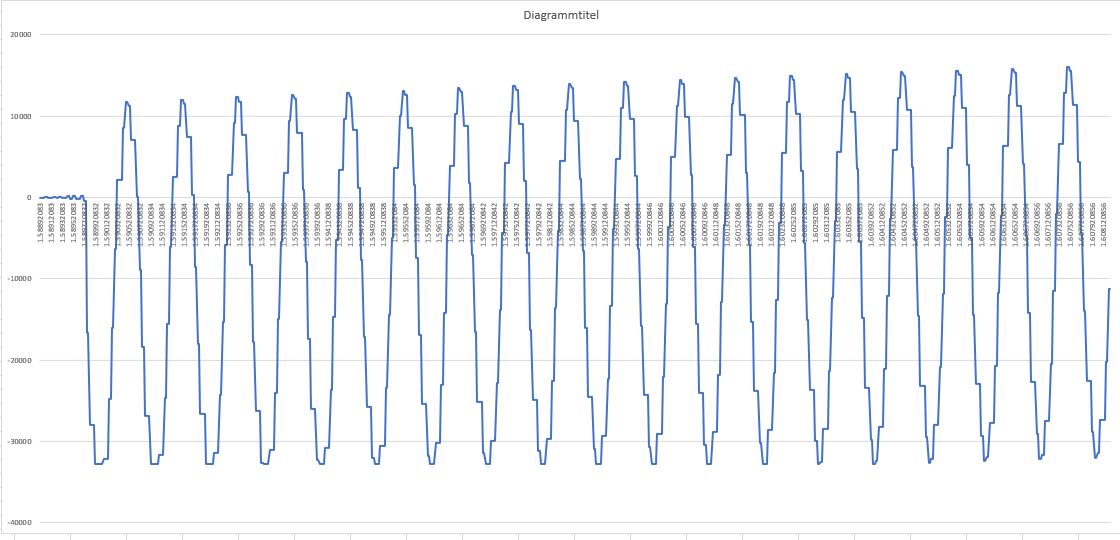
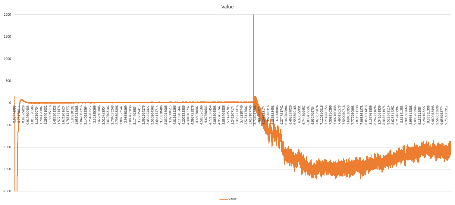
After powering up the device or restarting it in the debugger (thus reinitializing the codec) the codec sends too high values over I2S. The absolute values change if I change the mic gain, but the problem remains, the data is basically unusable for the first 3 minutes. Due to our hardware, I have to use the maximum gain if possible, which leads to the data values being maxed out for about a minute before they settle after the mentioned 3 minutes.

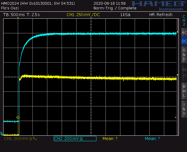
I have measured the mic signals going into the codec before and after the capacitor between both parts using an oscilloscope. The voltages seem to settle at their levels after about thirty seconds. Please also see the screenshots at the end.

The mic's input voltage is connected directly to the MICBIAS pin with 100n caps to ground. The only other external parts are 4.7u caps between the mic's outputs and the corresponding input pins of the codec.

The codec initialization procedure looks like this:
- Soft Reset
- Set Clocks
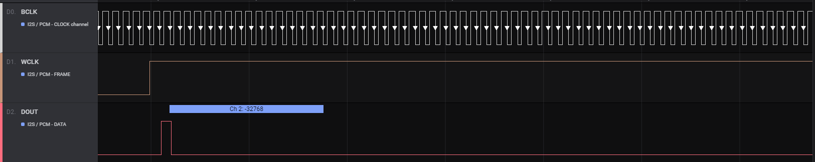
- Enable I2S interface
- Set ADC Input Mux
- Set mic bias to AVDD
- Set mic gain
- Enable ADC
- Enable codec output and set routing

I noticed that after setting the ADC mux the codec applies a voltage to the microphone input that increases further after setting the mic bias. Is that normal behavior? If I disconnect the codec, there's no DC part in the signal between codec and cap but only between mic and cap. If the codec is connected, there are different DC offsets before and after the cap.

Here are screenshots of a software reset without a power cycle, blue is between cap and codec, yellow between mic and cap:

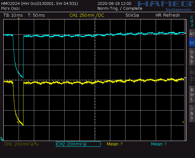
Here's a power cycle:

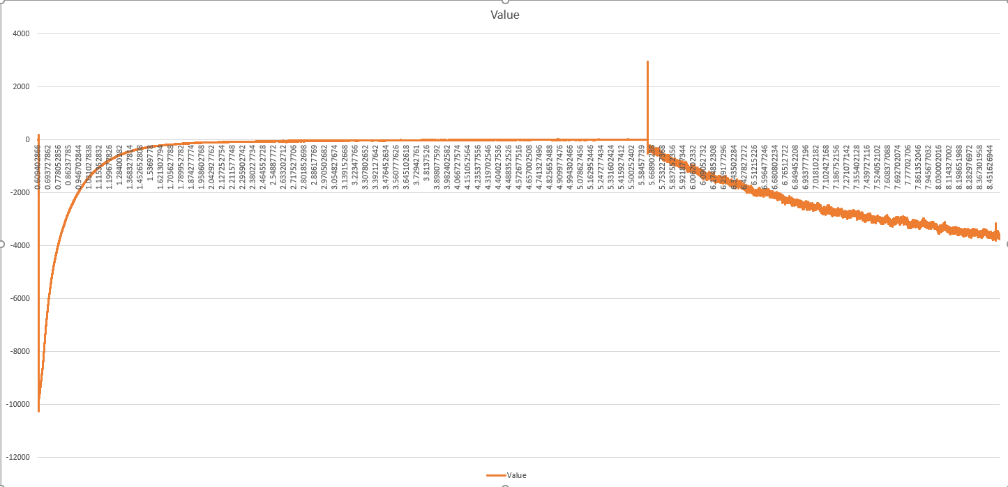
What I find really odd is that even after the voltages have settled the values I get over I2S continue to be way too high for about two and a half minutes.

Thanks for your help!

Edit: I forgot to mention that the values are not that high after a software reset and take less time to settle. They never max out like after a power cycle with the same gain setting and make sense after about a minute.

  • Hello Flo,

    Can you please share the following:

    - Schematic

    - Register configuration

    - scope shots of ASI bus showing BCLK, WCLK DOUT

    From your post, it sounds like there are caps on MICBIAS pin. Theses should be removed as MICBIAS is already a very clean signal and adding decoupling caps can produce unknown behavior.

    Regards,

    Aaron

  • Hi Aaron,

    here is the relevant part of the schematic:

    The caps were recommended by TDK in the microphone datasheet:

    I tried removing them though, unfortunately it didn't help.

    Here are the registers we write during setup (I transferred some of the values from our functions to actual values by hand, so it's possible there might be some errors):

    - Page 0, Reg 1 (software reset) - 0x01
    - Wait 1 ms
    - Page 0, Reg 4 (clock gen muxing) - PLLCLKIN_BCLK and CODECCLKIN_PLLCLK
    - Page 0, Reg 5 (pll p and r val) - P = 1, R = 1
    - Page 0, Reg 6 (pll j val) - J = 3
    - Page 0, Reg 7 & 8 (pll d val) - D = 2000
    - Page 0, Reg 11 (dac ndac_val) - NDAC = 5
    - Page 0, Reg 12 (dac mdac_val) - MDAC = 3
    - Page 0, Reg 13 & 14 (dac dosr_val) - DOSR = 128
    - Page 0, Reg 27 (codec interface ctrl) - interface = i2s, word length = 16, bclkout = false, wclkout = false
    - Page 0, Reg 18 (adc nadc_val) - NADC = 5
    - Page 0, Reg 19 (adc madc_val) - MADC = 3
    - Page 0, Reg 20 (adc aosr_val) - AOSR = 128
    - Page 1, Reg 48 (input selection for p terminal) - 0x50 (LP and RP 10kOhm)
    - Page 1, Reg 49 (input selection for m terminal) - 0
    - Page 1, Reg 46 (mic bias) - 0x0B (AVDD bias)
    - Page 1, Reg 47 (mic gain) - 0x77 (for testing, the problem exists with all gains)
    - Page 0, Reg 81 (adc digital mic) - 0x82 (enable adc, disable soft stepping)
    - Page 0, Reg 82 (fine adjust) - 0
    - some class D and DAC stuff

    I will add the scope shots later on.

    Edit: I don't know which part of the communication you would like to see, but here's a tiny bit of it:

    values.zip

    Here's a communication log exported from a logic analyzer.

  • Is there any new information concerning this problem?

  • Hello Flo,

    Apologies for the delay in response. 

    I took a look at the register setting you provided and have some comments/questions below:

     - What is the PLL input clock frequency and desired sample rate? If you are trying to get an Fs of 48kHz, it looks like your BCLK is ~28.8MHz or ~26.45MHz if trying to achieve an Fs of 44.1kHz. Can you please clarify?

     - Can you read P0, Register 39? These are the overflow flags and will inform the user if the ADC is being saturated. 

     - Can you try changing RIN to 20kohm or 40kohm and see if there is a difference?

    Regards,

    Aaron

  • Hi Aaron,

    - The BCLK frequency is 9.6 MHz. We're working with a sample rate of 16 kHz

    - The Overflow register value is 0x02 as long as the values are maxed out (ADC Barrel Shifter Output Overflow Flag), it changes to zero when the values begin to level out (but are still too high)

    - Changing RIN makes no difference

  • Hello Flo,

    It looks as if the PLL constraints are not being fully satisfied. While providing a BCLK of 9.6MHz and configuring the PLL as mentioned above will provide a 16kHz Fs, some constraints are being violated. When PLL is enabled and D ≠ 0, PLL_CLKIN/P should be between 10MHz and 20MHz. Additionally, PLL_CLKIN × J.D. × R / P should be between 80MHz and 110MHz. R x J should also be between 4 and 259. This constraint is violated as well. 

    With P = 1, PLL_CLKIN/P = 9.6MHz and with J = 3 and D = 2000, PLL_CLKIN × J.D. × R / P = 30.72MHz. Is the BCLK frequency flexible? If so, i would suggest increasing to 10MHz and changing some PLL values.

    Regards,

    Aaron

  • Hi Aaron,

    I changed our BCLK and PLL setup, now it should consider all guidelines. Unfortunately, the problem still exists.

    Our main CPU is a CC2640R2F, so I could change the BCLK frequency to 12 MHz. This however leads to the WCLK frequency being 20 kHz instead of 16 kHz, as the buffer size remained unchanged with 256 Byte. As far as I understand it, this should be no problem though.

    The PLL, ADC and DAC settings are now as follows:
    R = 1, J = 7, D = 6800, P = 1, NADC/DAC = 15, MADC/DAC = 3, A/DOSR = 128. This leads to a PLL_CLK of 92.16 MHz.

  • Hello Flo,

    PLL settings look to be satisfied now which is good. WCLK frequency should be equal to Fs but I don't think this will cause the problems you are experiencing. Moving forward, have you changed the AC coupling capacitor value? Currently I see it's 4.7uF. Data sheet recommends a value of 1uF. Something else to try would be to remove an onboard microphone and directly apply a 1Vpp, 1kHz siine wave.

    Is the issue you're experiencing happening on multiple boards or just one board?

    Regards,

    Aaron 

  • Hi Aaron,

    When I use the mic with a 1 uF cap as the only input with max gain, the problem persists, but seems to improve. It only takes about half a minute until the values are leveled out. But I guess this could also be due to using only one mic or a combination of other circumstances.

    When I use the sine wave input with a 1 uF cap and set the gain register to zero,  the problem seems to be gone. When I export the logic analyzer data into Excel and plot it, I get a relatively clean sine wave directly from the start. The DC offset is gone after about 2 seconds which is totally fine.

    I tried to turn down the mic gain and the values seemed to settle much faster. I thought I tried this before and the problem still existed, only with other values. So right now, without the 100n caps on the mic bias, with 1 uF caps in the mic path and without any mic pga gain, it seems to be working fine. Unfortunately, I will need mic gain to get useful values. Even if I change the mic gain while the system is running, the values will need about half a minute to settle to their new baseline. I tried enabling soft-stepping, but this didn't change anything. So, to conclude, I think the problem is the mic gain. Is there anything I can do to make the values settle faster after turning it up?

    Correction: I can change the gain on the fly without any artifacts. The problem only exists when reinitializing the codec. So I might just initialize it with a gain of zero and turn it to the max a few ms later. I'll have to try this on another hardware with two mics again though.

    Edit2: Well, I guess this is not the solution. Here's what happens if I initialize the codec with 0 dB mic pga and turn it up to 59.5 dB after 5 seconds:

    Here's what happens if I turn it up after 10 seconds:

    A bit more useful, but still not very much.

    Edit3: Here are the same measurements with the original hardware, I think we're getting somewhere :)

  • Hi Aaron, do you have any news? Anything that could be responsible for the problems after changing the gain?

  • Hello Flo,

    I took a look at the initialization process again and can you try to enable the ADC first and then the ADC PGA gain? While I don't think this will solve the issue, it is worth trying as that is how we recommend the record path configuration. Also, I am interested to see what happens if you operate the device at a faster sampling rate maybe 48kHz?

    Regards,

    Aaron

  • Quick FYI: I'm working on another project right now, but I will test your suggestions and report back ASAP.

  • Hi Aaron,

    unfortunately, the problem still exists. For details about setting the MIC PGA after activating the ADC, please see my post before your last post. When using the hardware I modified according to your guidance and a sample rate of 48 kHz, the values only max out for about 5 seconds, but we can't use a higher sample rate. Also, I would still like to understand why the problem occurs to fix it completely.

  • Hello Flo,

    Thanks for the update. Let me bring this up to some colleagues to see if we can through some ideas on a possible cause. I will get back to you soon.

    I appreciate the understanding and patience. 

    Regards,

    Aaron

  • Hello Flo,

    I had a discussion with a colleague and it was brought to my attention that some microphones exhibit behavior where upon startup, they are brought up to the MICBIAS level for a small period of time. This plus the high gain from the PGA may be saturating the ADC. Since the sample rate is on the lower end at 8kHz, it may take a bit for the ADC do come out of saturation. 

    Since you mentioned that the issue seems to get better when using a direct sine wave, I would like to know what the input level was when this was tested? It would be interesting to see if you saturate the ADC with a sine wave if you see the same behavior with the microphone. Can you also share a scope shot of the mic output when it is initialized?

    Regards,

    Aaron

  • Hi Aaron,

    Thanks for the additional ideas, I will try the sine wave and maybe also another microphone. I will also add the scope shot as soon as I can go back to this project. A problem I already noticed with scoping the mics is that the ADC will never come out of saturation as long as the scope is connected, but I will do my best.