This thread has been locked.

If you have a related question, please click the "Ask a related question" button in the top right corner. The newly created question will be automatically linked to this question.

TLV320ADC3140: Conditions to work with 32 bits 2-channel at 48kHz and 192kHz

Part Number: TLV320ADC3140

Hi,

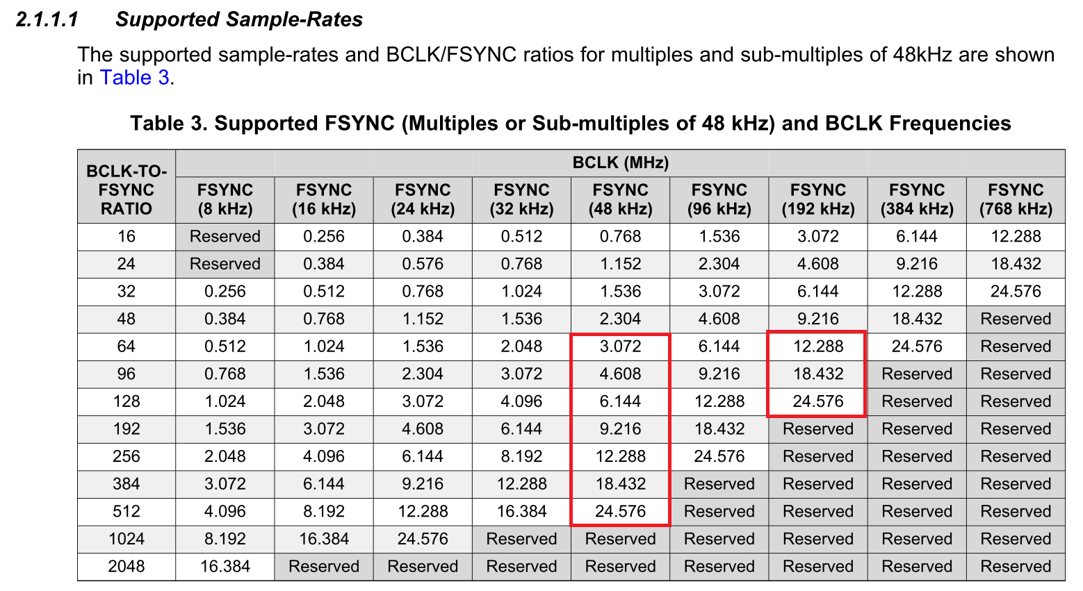
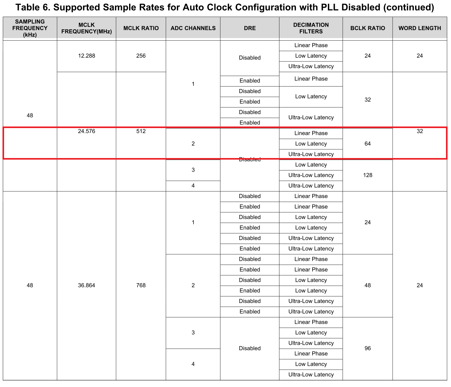
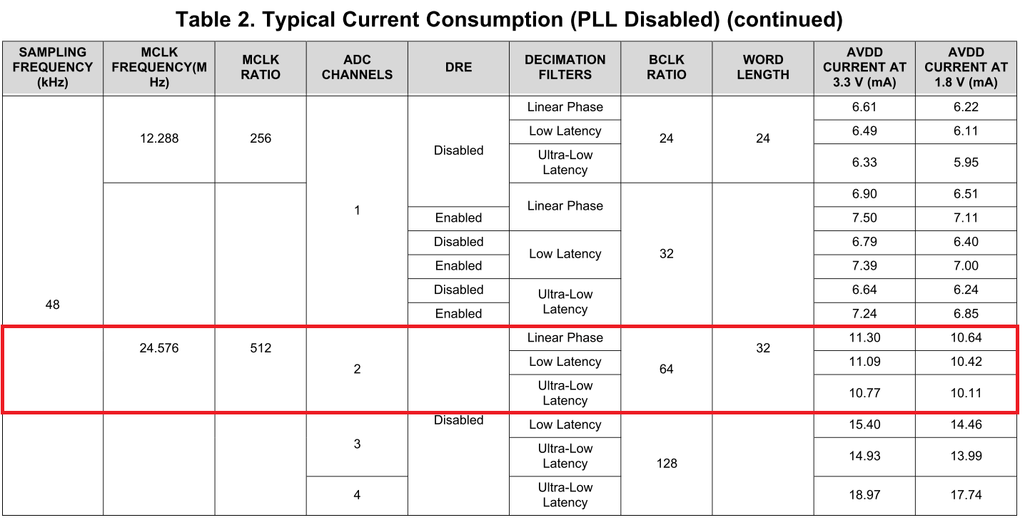
Could you please tell me all conditions to work with 32 bits 2-channel ADC at 48 kHz and 192 kHz properly?
According to the application note, it seems that TLV320ADC3140 properly works in the following cases.

(1) pll is enabled in master mode

(2) pll is disabled in master mode

(3) pll is disabled in slave mode


Best regards,
Kato

  • Hi Kato-san,

    I would suggest you refer to this app note for the supported features at various sample rates: 

    Best,

    Zak

  • Hi Zak-san,

    Thank you for the information.

    I have already confirmed that application note. However, it seems that there isn't mentioned in detail whether TLV320ADC3140 can work with 32 bits 2-channel ADC at 48 kHz and 192 kHz properly.
    So, could you please tell me all the setting conditions that TLV320ADC3140 can work with 32 bits 2-channel ADC at 48 kHz and 192 kHz?
    It would be helpful if you could provide a table with the appropriate settings to me.

    Best regards,
    Kato

  • Hi Kato-san,

    There is no problem operating 2 channels at 32bits. All of the modes described in the app note are valid for 32-bit word lengths and the app note describes how many channels are supported for a given sample rate based on the features you intend to use.

    Best,

    Zak

  • Hi Zak-san,

    Thank you for your reply.

    I understand and will contact you if I have additional questions.

    Best regards,
    Kato

  • Hi Zak-san,

    I have additional questions. If TLV320ADC3140 works properly under the following conditions, could you please tell me the required register settings in detail?

    Condition #1
    - ASI         = I2S
    - Mode        = Slave Mode
    - PLL         = Enable(Auto Clock Generation)
    - FS          = 48kHz
    - Word Length = 32bits
    - MCLK        = 12.288MHz
    - BCLK        = 3.072MHZ
    - FSYNC       = 48kHz

    Condition #2
    - ASI         = I2S
    - Mode        = Slave Mode
    - PLL         = Enable(Auto Clock Generation)
    - FS          = 48kHz
    - Word Length = 32bits
    - MCLK        = 24.576MHz
    - BCLK        = 3.072MHZ
    - FSYNC       = 48kHz

    Condition #3
    - ASI         = I2S
    - Mode        = Slave Mode
    - PLL         = Enable(Auto Clock Generation)
    - FS          = 192kHz
    - Word Length = 32bits
    - MCLK        = 24.576MHz
    - BCLK        = 12.288MHZ
    - FSYNC       = 192kHz

    Condition #4
    - ASI         = I2S
    - Mode        = Master Mode
    - PLL         = Enable(Auto Clock Generation)
    - FS          = 48kHz
    - Word Length = 32bits
    - MCLK        = 12.288MHz

    Condition #5
    - ASI         = I2S
    - Mode        = Master Mode
    - PLL         = Enable(Auto Clock Generation)
    - FS          = 48kHz
    - Word Length = 32bits
    - MCLK        = 24.576MHz

    Condition #6
    - ASI         = I2S
    - Mode        = Master Mode
    - PLL         = Enable(Auto Clock Generation)
    - FS          = 192kHz
    - Word Length = 32bits
    - MCLK        = 12.288MHz

    Condition #7
    - ASI         = I2S
    - Mode        = Master Mode
    - PLL         = Enable(Auto Clock Generation)
    - FS          = 192kHz
    - Word Length = 32bits
    - MCLK        = 24.576MHz

    Best regards,
    Kato

  • Hi Kato-san,

    The default settings for the device are 32-bit slave mode TDM with auto clock generation enabled. You just need to switch to I2S by writing 0x70 to register 0x07 and configure for master mode where appropriate. Also, when operating in master mode it is necessary to configure GPIO1 as the MCLK input by writing 0xa0 to register 0x21.

    I would strongly encourage you to download the PPC3 GUI for this device as it makes it very easy to familiarize yourself with the device and the register settings needed. You can change settings and monitor the I2C transactions directly using the I2C monitor integrated in the GUI.

    Best,

    Zak

  • Hi Zak-san,

    Thank you for your continuous support.

    I will ask our customer to test with PPC3 GUI. So, I would like to confirm just in case, but should TLV320ADC3140 be set to the master mode if using TLV320ADC3140 with 32 bits 2-channel ADC at 48 kHz and 192 kHz?

    Best regards,
    Kato

  • Hi Kato-san,

    The device can operate in either master or slave mode, it depends on which device you want to generate the audio clocks. If they choose to configure the device in master mode, we also have an app note that discusses how to set this up: 

    Best,

    Zak

  • Hi Zak-san,

    Thank you for the information.

    Yesterday, I requested PPC3 "ADCX140EVM-SW" plug-in to support our customer. However, I haven't been approved yet. So, could you please check it?

    Best regards,
    Kato

  • Hi Kato-san,

    I have not seen the request come through yet, sometimes there is a delay. If you can provide the email address associated with your myTI account we can make sure you are on the approved list.

    Best,

    Zak

  • Hi Zak-san,

    Thank you for your response.

    Could you please see my email address below and check the approved list?

    kato-s@macnica.co.jp

    Best regards,
    Kato

  • Kato-san,

    I have brought up your request and expect you should have access soon!

    Best,

    Zak

  • Hi Zak-san,

    Thank you for your support.

    My request has already been approved.

    Best regards,
    Kato