This thread has been locked.

If you have a related question, please click the "Ask a related question" button in the top right corner. The newly created question will be automatically linked to this question.

TPA3255: Reset pin voltage vs current characteristic

Part Number: TPA3255
Other Parts Discussed in Thread: TPS3802

Hello,

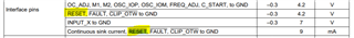
Is there an exact spec available of the voltage vs current applied to / drawn from the reset pin?

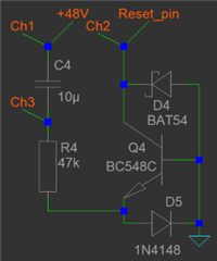
I want to drive the reset pin with a simple one-transistor-circuit during powering down.

Thanks,

Hans Verhees

  • Hans,

    I guess you mean this?

    BR

  • Frank,

    Thanks for your answer. But these are only the abs max data. What I would like to know is:

    • what is the pull up resistor value (internal)
    • or: how much current must I draw from the pin when in high state
    • and a which voltage/current combination will the pin go low

    As said before, I want to use a one-transistor-circuit, driven by the falling edge of the 48 Volt power supply, to pull the reset pin low. From that, I learned that I have to draw >300 uA before the pin goes low. But that is not quite what I expected. It looks like the pin is held high by an active circuit internally.

    I have some measurements available and also the circuit diagram. But inserting them in this post is not accepted! Don’t know why.

    Thanks,

    Hans Verhees

  • Hans,

    We need to check with our AE covering this device. We will reply you ASAP.

    BR

  • Hello,

     Today, suddenly, the system accepts pictures inserted in the text!!!!!!!!

    I try to drive the reset pin at switch off with a single transistor circuit (to suppress switch off "plops"). The input for the transistor is the falling edge of the power supply (48 V).

    However, during the first 150  milliseconds, the current drawn from the reset pin increases linearly, the voltage on the reset pin also drops linearly. This assumes a series resistor in the pin (3k3). Correct?

    But then, at around 300 uA drawn from the reset pin, the voltage suddenly drops to zero.

    Ch1: +48 V power supply

    Ch2: Reset pin

    Ch3: emitter Q4

    Ch4: Differential out of the amplifier

    Maybe this extra information is of any help for you?

    Gr.

    Hans Verhees

  • Hi Hans,

    Understood your request. Let me do some bench test to find out the I/O characteristic. 

    Will get back to you soon. Thanks!

    Regards,

    Sam

  • Hi Hans,

    Checked on bench, I didn't find any pull up/down resistance on RESET pin. It should be just a high-impedance input pin.

    It's quite an interesting design. Not sure if I fully captured your idea, but I believe you are trying to push a current flow to discharge the 10uF cap, forcing the BJT to work in linear region, thus sink a current from its collector to emitter.

    The point here is if the BJT really works in linear region. Although I can't clearly read the waveform in your post(it's too small), I got the feeling that it only start to sink the current when the RESET# pin is quickly pulled low. Please check. 

    BTW, could you share some detail on how you connected the RESET# pin in your design? Is it connected to a GPIO in your system? It may also have something to do with the GPIO characteristic.

    Thanks!

    Regards,

    Sam

  • Hi Sam,

    Thanks for your detailed reply.

    The board I am using is a two channel BTL design from a chinese manufacturer, bought via ebay. So I do not exactly know what the circuit diagram is. It seems the reset pin is left open but I am not sure about this! There is not so much more on the board, besides voltage regulators and audio input circuitry.

    From your measurements and description on the reset pin, it seems that either

    • something else is driving the reset pin in my board
    • my circuit doesn't behave as I expect

    I think the first point needs carefull examination of the circuit on the board in order to be sure that the second point is not the case here. I will also try to measure the reset pin current.

    Thanks,

    Hans Verhees

    PS, FYI:

    I changed the board from 2-ch BTL to one channel PBTL (two boards, two mono amplifiers each driving an Acoustat electrostatic loudspeaker). I moved all large through hole components to the opposite side of the board and mounted the board with the TPA3255 facing down on top of a heat sink. This  heat sink is in fact an aluminium part between the cabinet bottom and the TPA3255. Most recent change: I replaced the four inductors in the output filters to two inductors with lower resistance and better linearity (the PBTL configuration was then also changed from connecting the outputs together AFTER the LC filter to BEFORE the LC filter). The sound is much better now, more control.

    Since then, the plop at switching off is quite loud (louder than before). Therefor I now want to use the reset pin for this function.

  • Hi Sam,

    Problem solved.

    As said I was going to reexamine the board carefully and found a part that I previously thought to be part of the LED circuit (indicating fault etc.).  After scratching paint from tracks I found one pin of this part is connected to the reset pin of the TPA3255. The marking on the part (5-pin SOT323) is not visible but R's and C's connected to it point to a supply supervisor as used on the evaluation board. Probably a TPS3802?

    Although the effect of this supervisor at switch off is not very good!

    I connected my own one-transistor reset driver to the MR pin of the supervisor (from the datasheet it looks like that pin is a perfect fit for my circuit). The result is shown in the next picture:

    Ch2: Supply voltage

    Ch4: Differential output voltage of the amplifier with 1 kHz

    With a speaker connected, playing music, switching the amplifier off, there is absolutely no plop. The sound just disappears.

    Thanks for pointing me the right direction.

    Regards,

    Hans Verhees