This thread has been locked.

If you have a related question, please click the "Ask a related question" button in the top right corner. The newly created question will be automatically linked to this question.

CDCE913: CDCE913 SETTING

Part Number: CDCE913
Other Parts Discussed in Thread: CLOCKPRO

Hi ,


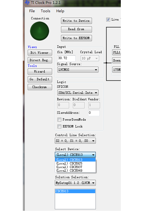
     I use the CDCE913 and use the clockPro to generate the register setting like blow:

     Input    frequence : LVCMOS 30.72MHz

     Output frequence : LVCMOS 24.576MHz


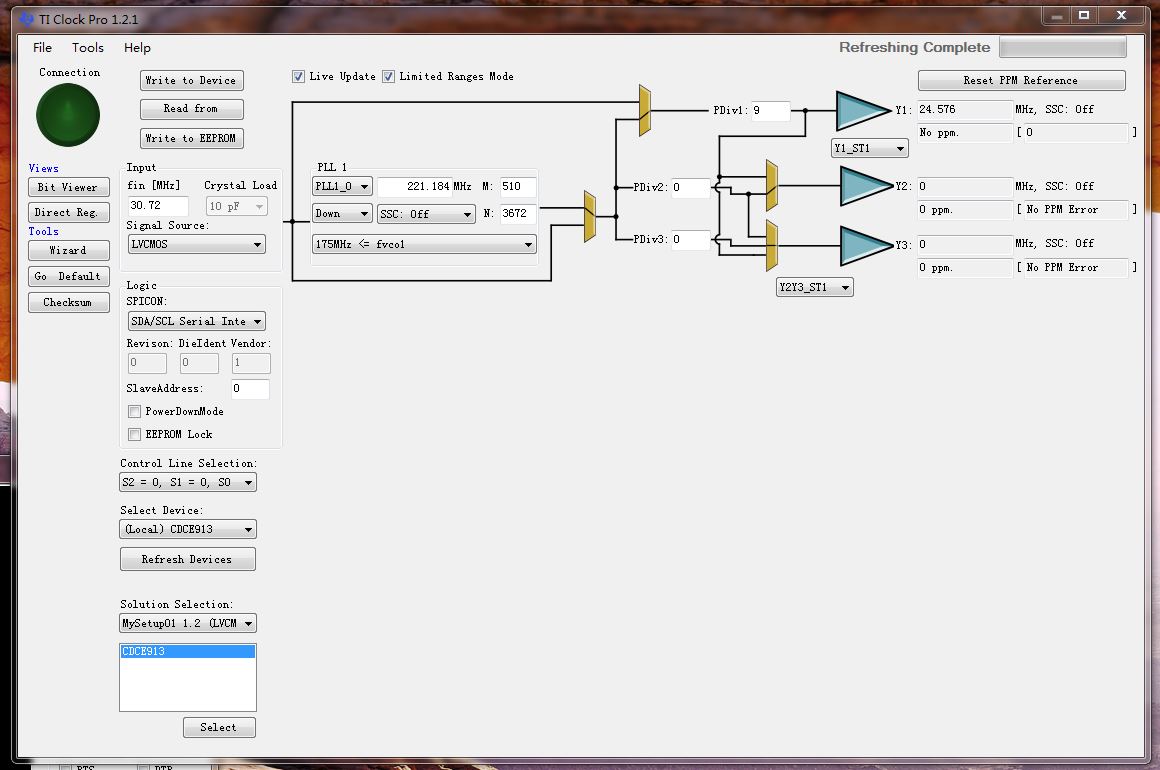
and generate the setting file is like:

Bit ==> 76543210
Byte 00 - 00000001
Byte 01 - 00001000
Byte 02 - 10110100
Byte 03 - 00001001
Byte 04 - 00000010
Byte 05 - 01010000
Byte 06 - 01000000
Byte 07 - 00000000
Byte 08 - 00000000
Byte 09 - 00000000
Byte 10 - 00000000
Byte 11 - 00000000
Byte 12 - 00000000
Byte 13 - 00000000
Byte 14 - 00000000
Byte 15 - 00000000
Byte 16 - 00000000
Byte 17 - 00000000
Byte 18 - 00000000
Byte 19 - 00000000
Byte 20 - 01101101
Byte 21 - 00000010
Byte 22 - 00000000
Byte 23 - 00000000
Byte 24 - 11100101
Byte 25 - 10001100
Byte 26 - 11000011
Byte 27 - 10001011
Byte 28 - 11100101
Byte 29 - 10001100
Byte 30 - 11000011
Byte 31 - 10001011


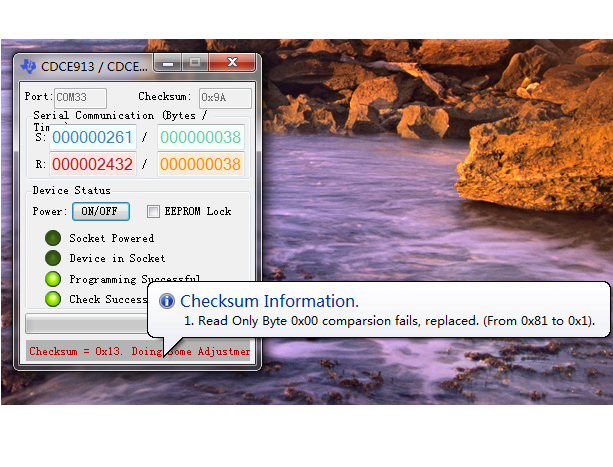
    And on PCB, I connect  the S0 to 1.8V ,but I can not got the output?

    Could you help me about this problem.

    Thanks!

Br,

Fei


  • Hi Fei,

    Your configuration looks correct. I would check that the voltage swing of the input clock you are providing meets the input requirements in the Recommended Operating Conditions table of the datasheet:

    Regards,

    -Tim

  • Hi ,


         Thank you for your reply!

         The voltage I think meets the requirements.

         Below do not care about the frequence ,just see the voltage .

         Any other problem I have ?

    Br,

    Fei


    Hi

  • Hi Fei,

    Can you provide the .isf configuration file that you used to program your device? (You may need to put it in a .zip folder to upload it to E2E).

    Regards,

    -Tim

  • Hi Tim,


        This is the ISF file .

        Thanks!

    Br,

    Fei

    test1.zip

    Br,

    Feitest1.zip

  • Hi Fei,

    The .isf file you have seems fine. I'm not sure what the issue could be.

    Are you testing this on an EVM or are you programming a loose part?

    If you are testing on an EVM, I noticed that in your screenshot, the connection light is off, which means there is no communication with the EVM. When ClockPro asks to select a device, be sure to select 'CDCE913', not '(Local) CDCE913)', since that sets the program to Demo Mode where it does not connect to the EVM.

    If you are programming a loose device using the programmer EVM, I would verify that the EEPROM is programmed correctly by pressing the 'EEPROM=' button to double check that the EEPROM is identical to the config file contents.

    Regards,

    -Tim

  • Hi Tim,

        Thank you for your reply!

         I use the CDCE9XXPROGRMEVM for programming and then put the chip on my PCB .

         Yes, I use 'EEPROM = ' to verify the chip after program it.

         The setting for 'CDCE913' I can not find this .


    So do I need some more setting ?

    Thanks!

    Br,

    Fei

  • Hi Tim,

          Right now ,I got the checksum fails from EVM,what should I do ?

          It is mean  I did not save the setting  into the EEPROM ,right?

          Thanks!

    Br,

    Fei

  • Hi Fei,

    You can ignore the message in the bottom status box. There is a bug where the checksum does not get written correctly so it rewrites it. As long as 'Programming Successful' and 'Check Successful' light up, the part has been programmed correctly.

    I am not sure what else is wrong. Would you be willing to share your schematic of the CDCE913?

    Regards,
    -Tim