Hi there:
Now we have a problem about LMX2592 using:
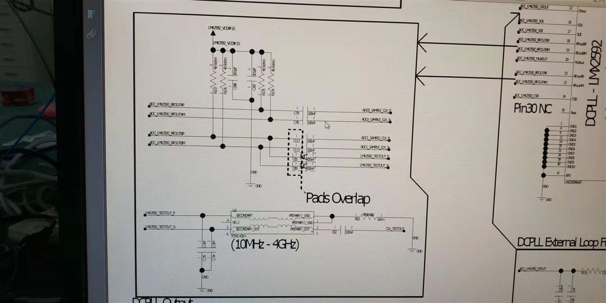
LMX2592 is used to generate two 3GHz sampling clocks connected to two ADC12DJ3200s, which are designed as below:
Where, the LMX2592 outputs are named as ADC_LMX2592_REFOUTAP/M and ADC_LMX2592_REFOUTBP/M. Behind the AC-coupling capacitors the two differential-ended clocks are connected to ADC12DJ3200s.
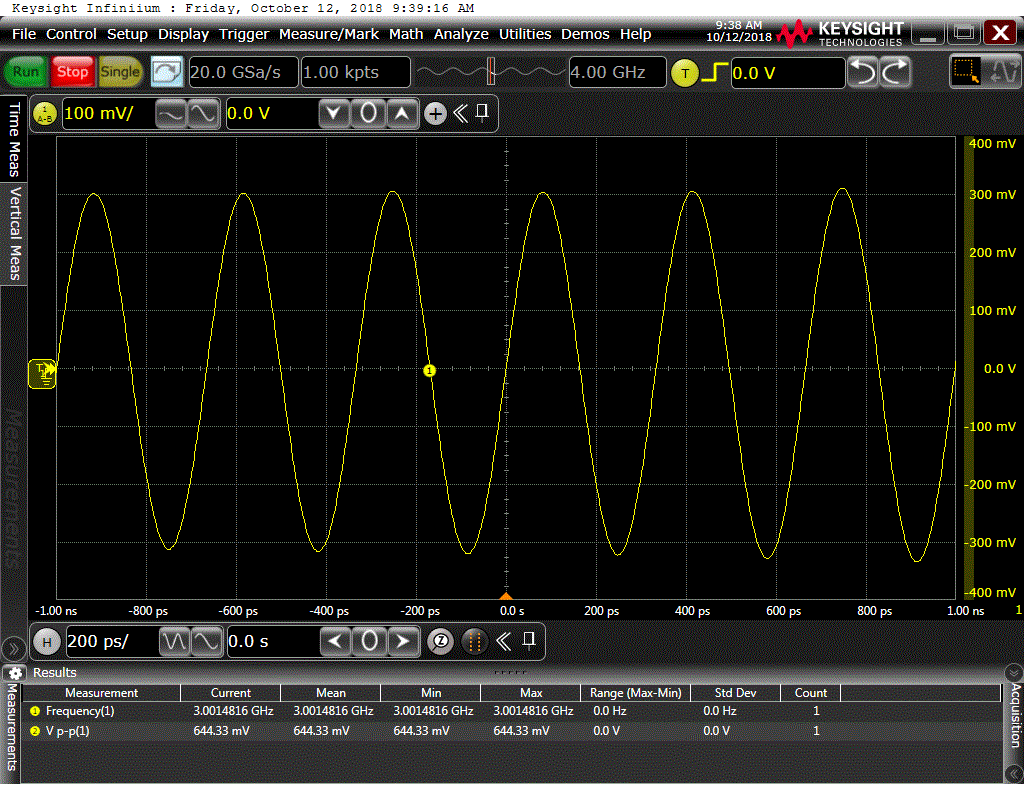
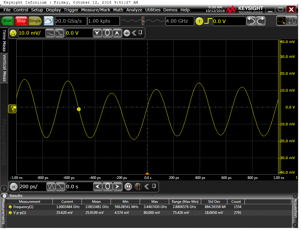
The measured Vpp of LMX2592 output is about 660mV using KEYSIGHT DSO90404A and the attached differential strobe, with the LMX2592 OUTA_POW register(REG46[13:8]) set to 0(decimal). The output the result is as below:
The 660mVpp (approximately -3.46dBm on 100ohm characteristic impedance differential lines) result is far smaller than the nominal rating in the datasheet: 8dBm@3GHz output frequency (Page7: Chapter 6.5 Electrical Characteristics). So, we set the register to a larger value, which was meant to make the output power larger, but the output power didnot increase as the datasheet says "increase power from 0 to 31" in the page 27:"Table41.R46 Register Field Descriptions".
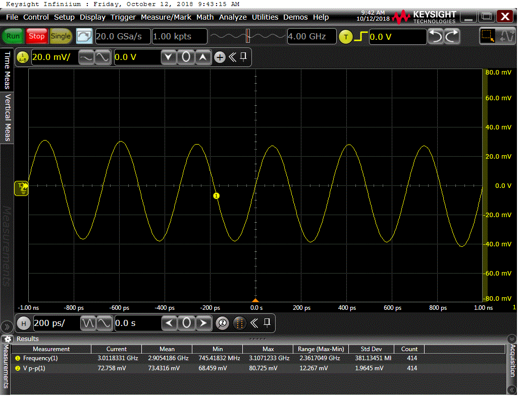
For example: when set to 8(decimal): about 70mVpp
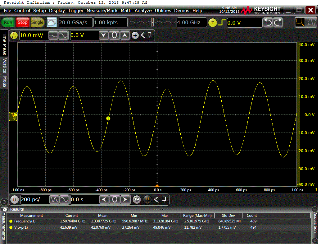
When set to 31(decimal): about 40mVpp
Even when set to 63(decimal): about 30mVpp
Result from the screenshots above, we can see the output power didnot increase with the register value got larger; Inversely the output power seemed to be decreasing with the register increasing.
So, I wanna know where maybe the problem exists, or what is the correct method to increase the output power of LMX2592.
Looking forward to your answer, thanks a lot~~~!
P.S. the register settings are as below: (register values are generated with the official tool "TICSPro")
0x002216, ////RESET
0x002214,
0x4000AF,
0x3F00A8,
0x3E0000,
0x3D0001,
0x3B0000,
0x3003FC,
0x2F00C0, ///0x2F00C0,///0x2F00CF, power enhance
0x2E00A3,//0x2E0023,///0x2E0F23, power enhance
0x26003C,
0x2D0000,
0x2C0000,
0x2B0000,
0x2A0000,
0x2903E8,///0x290001,///Denominator LSB of N-divider fraction
0x280000,
0x278204,////17
0x254000,
0x240418,////0x240C18,
0x23101B,
0x22C3EA,
0x214210,
0x204210,
0x1F0601,
0x1E0034,
0x1D0084,
0x1C2924,
0x190000,
0x180509,
0x178842,
0x162300,
0x14012C,
0x130965,
0x0E018C,
0x0D4000,
0x0C7001,
0x0B0018,
0x0A10D8,
0x090302,
0x081084,
0x0728B2,
0x041943,
0x020500,
0x010808,
0x00221C


