This thread has been locked.

If you have a related question, please click the "Ask a related question" button in the top right corner. The newly created question will be automatically linked to this question.

LMC555: LMC555

Part Number: LMC555
Other Parts Discussed in Thread: TLC555

Hi

We are having some issue matching calculated and real (tested) frequency output with LMC555 in 50% Duty Cycle Oscillator mode.

The formula for frequency calculation is: f = 1/(1.4 * Rc * C) [page 16 in the datasheet: LMC555 SNAS558M –FEBRUARY 2000–REVISED JULY 2016 ]

We used these components:

Rc = 4.7 MOhm; C = 1.8 pF 

f = 1/(1.4 * 4.7e+6 * 1.8e-12) = 84,431 Hz

f (tested) = 22,500 Hz

However, with other components:

Rc = 8 KOhm;  C = 1070 pF;

f = 1/(1.4 * 8E+3 * 1.07E-09) = 83,445 Hz

f (tested) = 84,200 Hz

Any idea what could be wrong?

  • User,

    Have you considered the parasitic capacitance of the LMC555 timer pins and the board traces?

    I haven't measured capacitance on LMC555 timer pins, but the similar TLC555 timer has 2pF on pins 2 and 6 for a total of 4pF. 

    At 8k ohms there may be a difference between (VDD - VOH) and (VOL - GND) making the output slightly higher than 50%

  • Hi Ron,

    Thank you for a prompt response.

    Ron Michallick said:

    User,

    Have you considered the parasitic capacitance of the LMC555 timer pins and the board traces?

    I haven't measured capacitance on LMC555 timer pins, but the similar TLC555 timer has 2pF on pins 2 and 6 for a total of 4pF. 

    At 8k ohms there may be a difference between (VDD - VOH) and (VOL - GND) making the output slightly higher than 50%

    We don't have equipment to measure such a low capacitance. We tested LMC555 with 4.7pF and variable resistor to create a frequency chart based on changing R.

    Also, looks like the formula in the datasheet doesn't take voltage Vs in consideration. I think this is wrong.

  • As long as the external capacitor is much bigger than the board and LMC555 capacitance then the parasitic capacitance won't matter. I suggest using at least 47pF although 100pF is better.

    The hysteresis thresholds for 555 timers are 1/3 VDD and 2/3VDD and the ramp rate on the timing cap is also based on VDD therefore the value of the power supply voltage does not matter.
  • Hi Ron,

    We have 4 DIP boards for testing with LMC555.
    We have configured test board with C = 47 pF, R = 126 kOhm.
    Vs stable 1.8V from a Vreg.
    According to the formula f=1/(1.4 x R x C) we should be getting 120,616 Hz in reality we get from 83,200 Hz to 84,600Hz

    We are lost here. How to calculate then real values for R and C for mass production run?
    Also if caps have tolerance 5% the resulting frequency will fluctuate 10%. This is too much for us. Are there any other clocks from TI with more stable output? preferably without Caps for frequency tuning.
  • User,

    1.8V is close to the bottom of the LMC555 operating voltage. Therefore propagation delays will be greater than other supply voltage. Multiple try tuning could work but the variance would likely be too high for your needs.

    Perhaps a crystal and driver would work better.

    Driver: SN74LVC1GX04 and crystal 

    www.digikey.com/.../479641

  • Hi Ron,

    Thank you for a prompt response.

    We have an option to go with 2.5V or even 2.8V
    What is the best voltage for LMC555 in terms of reaching stable frequency output at 84,200 KHz.
    Could you recommend formula for calculating C and R at 2.5V?
    Also, we couldn't find PCB layout guidelines in datasheet for DCBGA package. Does it exist?
  • You could try 180pF and 41.2k ohms for 84.2kHz
    I measured 84.46kHz with 175pF and 42.2k ohms. With 180pF center that make Rcenter=40.9k.
    41.2k is closet 1% resistor. That is a 1.5us difference between calculated period and actual measured.

    If the difference changed by +/-20% (reasonable estimate) then that would make range 82.1k to 86.4kHz
  • Hi Ron,

    Thank you for the test. How did you calculate f=84.2kHz with C=180pF and Rc=41.2k ohms?

    The formula is: f = 1/(1.4 * Rc * C) [page 16 in the datasheet: LMC555 SNAS558M –FEBRUARY 2000–REVISED JULY 2016 ]

    with Rc = 41.2 kOhm; C = 180 pF f = 1/(1.4 * 41.2e+3 * 180e-12) = 96,317 Hz

    Thanks,
    Vlad
  • Vlad,

    To get initial test value I used TLC555 design calculator spreadsheet. It is for 2 resistor and pin 7 usage so it is not totally accurate for 1 resistor pin 3 usage. That gave me a starting point  for bench tests. I have a setup where I can change values easily and I fine tuned the resistor value.

    Copy of TLC555astable_b.xls

  • Vlad,

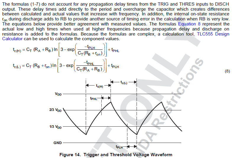
    Here are the equations for RA, Rb, C a-stable, however Tplh and Tphl need to be known and they are not in the data sheet for LMC555.

    RB = RC and RA = 0 for 50% circuit