Other Parts Discussed in Thread: LMX2572, USB2ANY
Hi,
We are using your evaluation board of synthesizer LMX2572EVM. I use the 100 MHz
reference oscillator. I am making a sweep frequency from 5.0 GHz to 5.1 GHz with
51 step frequency points at the maximum possible speed waiting for the device to
lock.
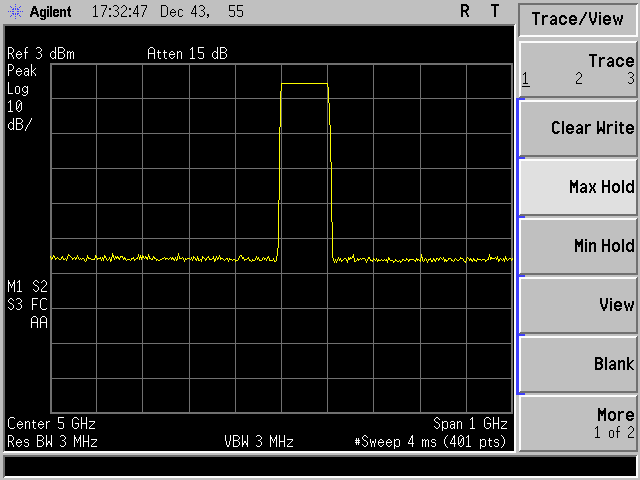
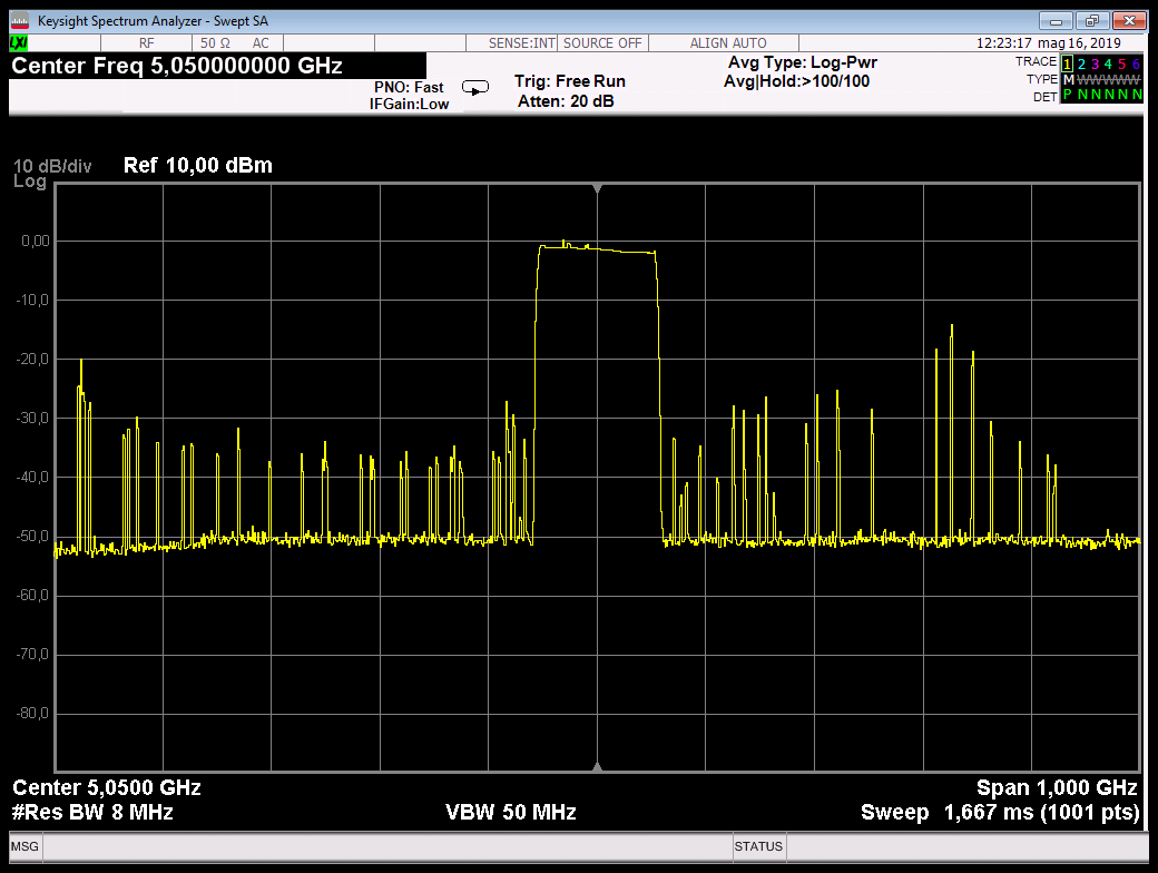
I initialized the device with the default registers for the VCO frequency of
5.050 GHz this is the output:
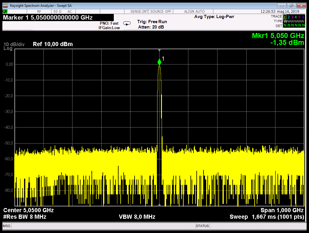

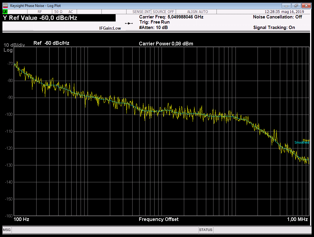
Is good output.
Now I want to implement a frequency sweep from 5.0 GHz to 5.1 GHz.
The device locks for all 51 frequencies without any problem, using the following
table of pre-calculated values with sequence :
start frequency: 5000000000
stop frequency: 5100000000
point : 51
step frequency: 2000000
index, INT, NUM, DEN, PFD, VCO Calc, VCO Real, Error, RFDIV, CHDIV, MUX, RF Output
0, 50, 0, 1, 100000000, 5000000000.0000000000, 5000000000.0000000000, +0.0000000000, 1, 0, VCO, 5000000000.0000000000
1, 50, 1, 50, 100000000, 5002000000.0000000000, 5002000000.0000000000, +0.0000000000, 1, 0, VCO, 5002000000.0000000000
2, 50, 1, 25, 100000000, 5004000000.0000000000, 5004000000.0000000000, +0.0000000000, 1, 0, VCO, 5004000000.0000000000
3, 50, 3, 50, 100000000, 5006000000.0000000000, 5006000000.0000000000, +0.0000000000, 1, 0, VCO, 5006000000.0000000000
4, 50, 2, 25, 100000000, 5008000000.0000000000, 5008000000.0000000000, +0.0000000000, 1, 0, VCO, 5008000000.0000000000
5, 50, 1, 10, 100000000, 5010000000.0000000000, 5010000000.0000000000, +0.0000000000, 1, 0, VCO, 5010000000.0000000000
6, 50, 3, 25, 100000000, 5012000000.0000000000, 5012000000.0000000000, +0.0000000000, 1, 0, VCO, 5012000000.0000000000
7, 50, 7, 50, 100000000, 5014000000.0000000000, 5014000000.0000000000, +0.0000000000, 1, 0, VCO, 5014000000.0000000000
8, 50, 4, 25, 100000000, 5016000000.0000000000, 5016000000.0000000000, +0.0000000000, 1, 0, VCO, 5016000000.0000000000
9, 50, 9, 50, 100000000, 5018000000.0000000000, 5018000000.0000000000, +0.0000000000, 1, 0, VCO, 5018000000.0000000000
10, 50, 1, 5, 100000000, 5020000000.0000000000, 5020000000.0000000000, +0.0000000000, 1, 0, VCO, 5020000000.0000000000
11, 50, 11, 50, 100000000, 5022000000.0000000000, 5022000000.0000000000, +0.0000000000, 1, 0, VCO, 5022000000.0000000000
12, 50, 6, 25, 100000000, 5024000000.0000000000, 5024000000.0000000000, +0.0000000000, 1, 0, VCO, 5024000000.0000000000
13, 50, 13, 50, 100000000, 5026000000.0000000000, 5026000000.0000000000, +0.0000000000, 1, 0, VCO, 5026000000.0000000000
14, 50, 7, 25, 100000000, 5028000000.0000000000, 5028000000.0000000000, +0.0000000000, 1, 0, VCO, 5028000000.0000000000
15, 50, 3, 10, 100000000, 5030000000.0000000000, 5030000000.0000000000, +0.0000000000, 1, 0, VCO, 5030000000.0000000000
16, 50, 8, 25, 100000000, 5032000000.0000000000, 5032000000.0000000000, +0.0000000000, 1, 0, VCO, 5032000000.0000000000
17, 50, 17, 50, 100000000, 5034000000.0000000000, 5034000000.0000000000, +0.0000000000, 1, 0, VCO, 5034000000.0000000000
18, 50, 9, 25, 100000000, 5036000000.0000000000, 5036000000.0000000000, +0.0000000000, 1, 0, VCO, 5036000000.0000000000
19, 50, 19, 50, 100000000, 5038000000.0000000000, 5038000000.0000000000, +0.0000000000, 1, 0, VCO, 5038000000.0000000000
20, 50, 2, 5, 100000000, 5040000000.0000000000, 5040000000.0000000000, +0.0000000000, 1, 0, VCO, 5040000000.0000000000
21, 50, 21, 50, 100000000, 5042000000.0000000000, 5042000000.0000000000, +0.0000000000, 1, 0, VCO, 5042000000.0000000000
22, 50, 11, 25, 100000000, 5044000000.0000000000, 5044000000.0000000000, +0.0000000000, 1, 0, VCO, 5044000000.0000000000
23, 50, 23, 50, 100000000, 5046000000.0000000000, 5046000000.0000000000, +0.0000000000, 1, 0, VCO, 5046000000.0000000000
24, 50, 12, 25, 100000000, 5048000000.0000000000, 5048000000.0000000000, +0.0000000000, 1, 0, VCO, 5048000000.0000000000
25, 50, 1, 2, 100000000, 5050000000.0000000000, 5050000000.0000000000, +0.0000000000, 1, 0, VCO, 5050000000.0000000000
26, 50, 13, 25, 100000000, 5052000000.0000000000, 5052000000.0000000000, +0.0000000000, 1, 0, VCO, 5052000000.0000000000
27, 50, 27, 50, 100000000, 5054000000.0000000000, 5054000000.0000000000, +0.0000000000, 1, 0, VCO, 5054000000.0000000000
28, 50, 14, 25, 100000000, 5056000000.0000000000, 5056000000.0000000000, +0.0000000000, 1, 0, VCO, 5056000000.0000000000
29, 50, 29, 50, 100000000, 5058000000.0000000000, 5058000000.0000000000, +0.0000000000, 1, 0, VCO, 5058000000.0000000000
30, 50, 3, 5, 100000000, 5060000000.0000000000, 5060000000.0000000000, +0.0000000000, 1, 0, VCO, 5060000000.0000000000
31, 50, 31, 50, 100000000, 5062000000.0000000000, 5062000000.0000000000, +0.0000000000, 1, 0, VCO, 5062000000.0000000000
32, 50, 16, 25, 100000000, 5064000000.0000000000, 5064000000.0000000000, +0.0000000000, 1, 0, VCO, 5064000000.0000000000
33, 50, 33, 50, 100000000, 5066000000.0000000000, 5066000000.0000000000, +0.0000000000, 1, 0, VCO, 5066000000.0000000000
34, 50, 17, 25, 100000000, 5068000000.0000000000, 5068000000.0000000000, +0.0000000000, 1, 0, VCO, 5068000000.0000000000
35, 50, 7, 10, 100000000, 5070000000.0000000000, 5070000000.0000000000, +0.0000000000, 1, 0, VCO, 5070000000.0000000000
36, 50, 18, 25, 100000000, 5072000000.0000000000, 5072000000.0000000000, +0.0000000000, 1, 0, VCO, 5072000000.0000000000
37, 50, 37, 50, 100000000, 5074000000.0000000000, 5074000000.0000000000, +0.0000000000, 1, 0, VCO, 5074000000.0000000000
38, 50, 19, 25, 100000000, 5076000000.0000000000, 5076000000.0000000000, +0.0000000000, 1, 0, VCO, 5076000000.0000000000
39, 50, 39, 50, 100000000, 5078000000.0000000000, 5078000000.0000000000, +0.0000000000, 1, 0, VCO, 5078000000.0000000000
40, 50, 4, 5, 100000000, 5080000000.0000000000, 5080000000.0000000000, +0.0000000000, 1, 0, VCO, 5080000000.0000000000
41, 50, 41, 50, 100000000, 5082000000.0000000000, 5082000000.0000000000, +0.0000000000, 1, 0, VCO, 5082000000.0000000000
42, 50, 21, 25, 100000000, 5084000000.0000000000, 5084000000.0000000000, +0.0000000000, 1, 0, VCO, 5084000000.0000000000
43, 50, 43, 50, 100000000, 5086000000.0000000000, 5086000000.0000000000, +0.0000000000, 1, 0, VCO, 5086000000.0000000000
44, 50, 22, 25, 100000000, 5088000000.0000000000, 5088000000.0000000000, +0.0000000000, 1, 0, VCO, 5088000000.0000000000
45, 50, 9, 10, 100000000, 5090000000.0000000000, 5090000000.0000000000, +0.0000000000, 1, 0, VCO, 5090000000.0000000000
46, 50, 23, 25, 100000000, 5092000000.0000000000, 5092000000.0000000000, +0.0000000000, 1, 0, VCO, 5092000000.0000000000
47, 50, 47, 50, 100000000, 5094000000.0000000000, 5094000000.0000000000, +0.0000000000, 1, 0, VCO, 5094000000.0000000000
48, 50, 24, 25, 100000000, 5096000000.0000000000, 5096000000.0000000000, +0.0000000000, 1, 0, VCO, 5096000000.0000000000
49, 50, 49, 50, 100000000, 5098000000.0000000000, 5098000000.0000000000, +0.0000000000, 1, 0, VCO, 5098000000.0000000000
50, 51, 0, 1, 100000000, 5100000000.0000000000, 5100000000.0000000000, +0.0000000000, 1, 0, VCO, 5100000000.0000000000
I wrote a small program that sends these frequency points continuously to create
a frequency sweep.
Flow logic:
Init_LMX2572
for(index = 0; index < 51; index++)
{
...
Send R75/R45/R43/R42/R39/R38/R37/R36
...
Start AutoCal wiht send R0
...
Waiting Lock
...
Continue Next Point
}
At the change of a frequency, none in particular, on the spectrum analyzer I see
spurs frequency that I think should not be there. These spurs do not seem to have
any relation to the frequency I am setting.
I activated :
- R0 "OUT_MUTE" Mutes RF outputs (RFoutA and RFoutB) when the VCO is calibrating
- R78 "QUICK_RECAL_EN" This sets the initial VCO starting calibration values.
Especially useful if the frequency change is smaller, say < 50 MHz or so.
Default value:
//
// Output Frequency 5050 MHz
//
const unsigned int LMX2572_Default_Config[126] =
{
0x00231C, // R0
0x010808, // R1
0x020500, // R2 (fixed)
0x030782, // R3 (fixed)
0x040A43, // R4 (fixed)
0x0530C8, // R5
0x06C802, // R6
0x0700B2, // R7
0x082000, // R8
0x090004, // R9
0x0A10F8, // R10
0x0BB018, // R11 Port-R divider PLL_R ( /1 )
0x0C5001, // R12 Pre-R divider PLL_R_PRE ( /1 )
0x0D4000, // R13 (fixed)
0x0E1820, // R14 Charge Pump Gain
0x0F060E, // R15 (fixed)
0x100080, // R16
0x110096, // R17
0x120064, // R18 (fixed)
0x1327B7, // R19
0x144848, // R20
0x150409, // R21 (fixed)
0x160001, // R22 (fixed)
0x17007C, // R23 (fixed)
0x18071A, // R24 (fixed)
0x190624, // R25 (fiexd)
0x1A0808, // R26 (fixed)
0x1B0002, // R27 (fixed)
0x1C0488, // R28 (fixed)
0x1D0000, // R29 (fiexd)
0x1E18A6, // R30 (fixed)
0x1FC3E6, // R31 (fixed)
0x2005BF, // R32 (fixed)
0x211E01, // R33 (fixed)
0x220010, // R34 N divider PLL_N[18:16]
0x230004, // R35 (fixed)
0x240032, // R36 N divider PLL_N[15:0]
0x250305, // R37 PFD Delay Select change with N divider
0x260000, // R38 PLL Denominator PLL_DEN[31:16]
0x2703E8, // R39 PLL Denominator PLL_DEN[15:0]
0x280000, // R40 MASH Seed [31:16]
0x290000, // R41 MASH Seed [15:0]
0x2A0000, // R42 PLL Numerator PLL_NUM[31:16]
0x2B01F4, // R43 PLL Numerator PLL_NUM[15:0]
0x2C1FA3, // R44 RF Output Power Ch. A / Mash Order
0x2DCE1F, // R45 RF Output Divider A / RF Output Power Ch. B
0x2E07F0, // R46 RF Output Divider B
0x2F0300, // R47 (fixed)
0x3003E0, // R48 (fixed)
0x314180, // R49 (fixed)
0x320080, // R50 (fixed)
0x330080, // R51 (fixed)
0x340421, // R52 (fixed)
0x350000, // R53 (fixed)
0x360000, // R54 (fixed)
0x370000, // R55 (fixed)
0x380000, // R56 (fixed)
0x390020, // R57 (fixed)
0x3A9001, // R58 SYNC
0x3B0001, // R59 Lock Type
0x3C03E8, // R60 Lock detect delay
0x3D00A8, // R61 (fixed)
0x3E60AF, // R62 Dobule Buffer Enable for other register
0x3F0000, // R63 (fixed)
0x401388, // R64 (fixed)
0x410000, // R65 (fixed)
0x4201F4, // R66 (fixed)
0x430000, // R67 (fixed)
0x4403E8, // R68 (fixed)
0x450000, // R69 Mash Reset Counter [31:16]
0x46C350, // R70 Mash Reset Counter [15:0]
0x470081, // R71 SysRef
0x480001, // R72 SysRef Divider
0x49003F, // R73 SysRef Adjustment
0x4A0000, // R74 SysRef Repeat
0x4B0800, // R75 RF Channel Divider
0x4C000C, // R76 (fixed)
0x4D0000, // R77 (fixed)
0x4E0201, // R78 VCO Capture Control
0x4F0000, // R79 Ramp Threshold [31:16]
0x500000, // R80 Ramp Threshold [15:0]
0x510000, // R81 Ramp Limit High [32]
0x520000, // R82 Ramp Limit High [31:16]
0x530000, // R83 Ramp Limit High [15:0]
0x540000, // R84 Ramp Limit Low [32]
0x550000, // R85 Ramp Limit Low [31:16]
0x560000, // R86 Ramp Limit Low [15:0]
0x570000, // R87 (fixed)
0x580000, // R88 (fixed)
0x590000, // R89 (fixed)
0x5A0000, // R90 (fixed)
0x5B0000, // R91 (fixed)
0x5C0000, // R92 (fixed)
0x5D0000, // R93 (fixed)
0x5E0000, // R94 (fixed)
0x5F0000, // R95 (fixed)
0x600000, // R96 Ramp Burst Count
0x610000, // R97 Ramp 0 Config
0x620000, // R98 Ramp 0 Increment Config
0x630000, // R99 Ramp 0 Increment [15:0]
0x640000, // R100 Ramp 0 Length
0x650000, // R101 Ramp 1 Config
0x660000, // R102 Ramp 1 Increment Config
0x670000, // R103 Ramp 1 Increment [15:0]
0x680000, // R104 Ramp 1 Length
0x694440, // R105 Ramp Delay
0x6A0007, // R106 Ramp Trigger
0x6B0000, // R107 (fixed) (read only)
0x6C0000, // R108 (fixed) (read only)
0x6D0000, // R109 (fixed) (read only)
0x6E0000, // R110 Lock Tune / VCO Select (read only)
0x6F0000, // R111 VCO Control (read only)
0x700000, // R112 VCO DAC I Set (read only)
0x710000, // R113 (fixed) (read only)
0x727802, // R114 FSK mode
0x730000, // R115 FSK deviation scale
0x740000, // R116 FSK deviation 0
0x750000, // R117 FSK deviation 1
0x760000, // R118 FSK deviation 2
0x770000, // R119 FSK deviation 3
0x780000, // R120 FSK deviation 4
0x790000, // R121 FSK deviation 5
0x7A0000, // R122 FSK deviation 6
0x7B0000, // R123 FSK deviation 7
0x7C0000, // R124 FSK SPI Fast mode
0x7D2288 // R125 (fixed)
};
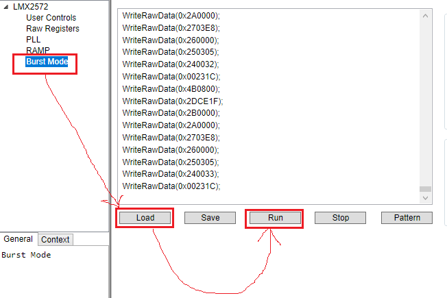
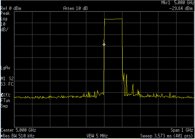
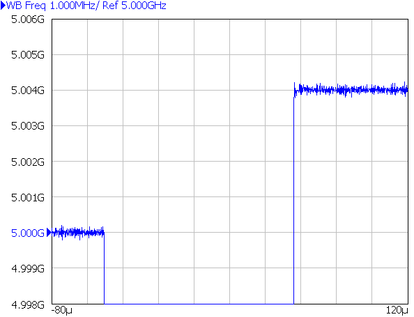
With frequency sweep I see this:
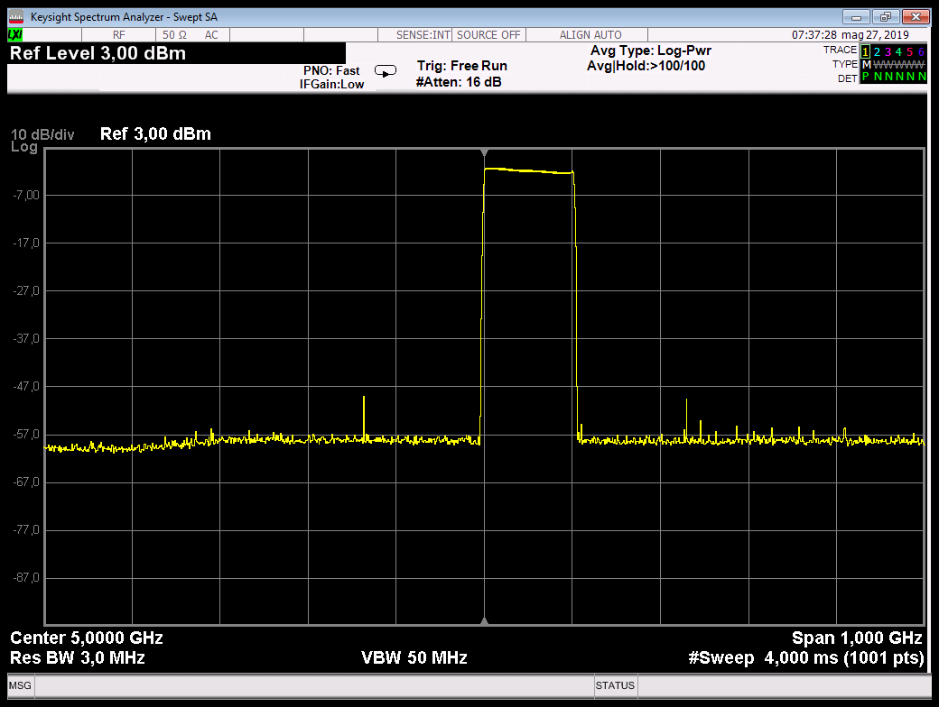
With frequency hop I see this:
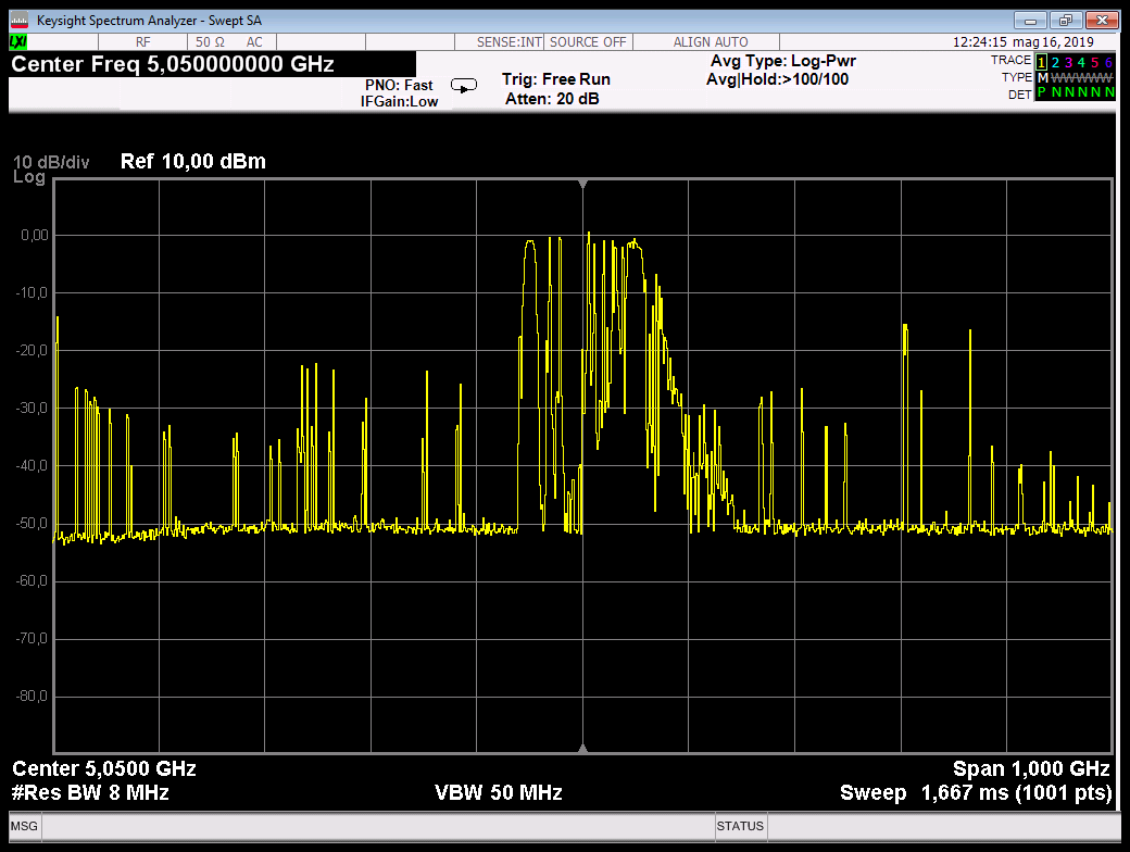
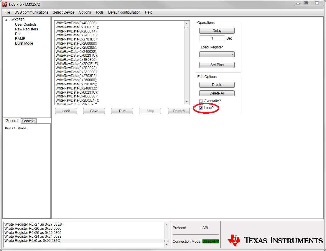
With update CW frequency continuously I see this:

Even making a very slow frequency change (example every second) the spurs are
presented in the same way.
The problem of what could be derived ?
Thanks very much.