This thread has been locked.

If you have a related question, please click the "Ask a related question" button in the top right corner. The newly created question will be automatically linked to this question.

LMX2572: What to expect about far-off spurs

Part Number: LMX2572
Other Parts Discussed in Thread: LMX2594, ,

Hi,

We're evaluating synthesizers for a wideband receiver. It's a superheterodyne receiver with two local oscillators, and the first one needs to tune to whatever frequency in a continuous ~3GHz range or in another continuous, non overlapping 2GHz range. (for example, it might have to tune to any frequency from 0.5 to 2.5 GHz and also from 3 to 6 GHz).

We purchased LMX2594 and LMX2572 EVM's as both of these devices looked very good. We've been working with LMX2594 for a while and we've created an optimization routine with several PFD's  and we've been able to reduce close-in spurs to acceptable levels (-80dBc typical) in every frequency we try by adjusting MASH order, PFD, and sometimes MASH seed. We also noted that sometimes changing the output power dramatically reduces some spurs.

The issue comes from far-off spurs, as they are quite nasty. We've measured -50dBc VCO-related spurs 1GHz away from the carrier and similar stuff (in LMX2594) and that's not good for our application. Could be solved with an LO filterbank but we first need to know what to expect in order to design such filter.

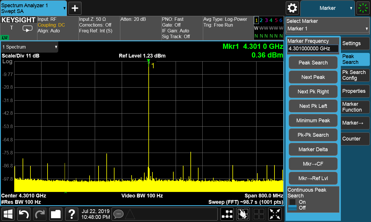
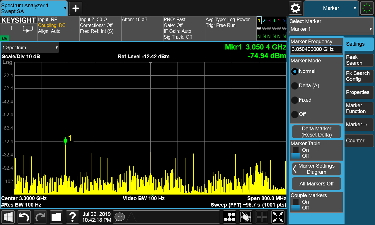
We recently got the LMX2572 EVM to check if the far-off spur performance is better, as the charge pump current is lower and Kvco is more linear. Here's a measurement taken from an LMX2572EVM set at 4301 MHz from a 125 MHz reference (the one that comes with the EVM) at 800 MHz span with no optimization. First picture is the carrier, second picture 1GHz away from it:

The register settings are these:

0647.HexRegisterValues.txt
R125	0x7D2288
R124	0x7C0000
R123	0x7B0000
R122	0x7A0000
R121	0x790000
R120	0x780000
R119	0x770000
R118	0x760000
R117	0x750000
R116	0x740000
R115	0x730000
R114	0x727802
R113	0x710000
R112	0x700000
R111	0x6F0000
R110	0x6E0000
R109	0x6D0000
R108	0x6C0000
R107	0x6B0000
R106	0x6A0007
R105	0x694440
R104	0x680000
R103	0x670000
R102	0x660000
R101	0x650000
R100	0x640000
R99	0x630000
R98	0x620000
R97	0x610000
R96	0x600000
R95	0x5F0000
R94	0x5E0000
R93	0x5D0000
R92	0x5C0000
R91	0x5B0000
R90	0x5A0000
R89	0x590000
R88	0x580000
R87	0x570000
R86	0x560000
R85	0x550000
R84	0x540000
R83	0x530000
R82	0x520000
R81	0x510000
R80	0x500000
R79	0x4F0000
R78	0x4E0001
R77	0x4D0000
R76	0x4C000C
R75	0x4B0800
R74	0x4A0000
R73	0x49003F
R72	0x480001
R71	0x470081
R70	0x46C350
R69	0x450000
R68	0x4403E8
R67	0x430000
R66	0x4201F4
R65	0x410000
R64	0x401388
R63	0x3F0000
R62	0x3E00AF
R61	0x3D00A8
R60	0x3C03E8
R59	0x3B0001
R58	0x3A9001
R57	0x390020
R56	0x380000
R55	0x370000
R54	0x360000
R53	0x350000
R52	0x340421
R51	0x330080
R50	0x320080
R49	0x314180
R48	0x3003E0
R47	0x2F0300
R46	0x2E07F0
R45	0x2DCE1F
R44	0x2C1FA3
R43	0x2B0198
R42	0x2A0000
R41	0x290000
R40	0x280000
R39	0x2703E8
R38	0x260000
R37	0x250205
R36	0x240022
R35	0x230004
R34	0x220010
R33	0x211E01
R32	0x2005BF
R31	0x1FC3E6
R30	0x1E18A6
R29	0x1D0000
R28	0x1C0488
R27	0x1B0002
R26	0x1A0808
R25	0x190624
R24	0x18071A
R23	0x17007C
R22	0x160001
R21	0x150409
R20	0x144848
R19	0x1327B7
R18	0x120064
R17	0x110096
R16	0x100080
R15	0x0F060E
R14	0x0E1810
R13	0x0D4000
R12	0x0C5001
R11	0x0BB018
R10	0x0A10F8
R9	0x090004
R8	0x082000
R7	0x0700B2
R6	0x06C802
R5	0x0530C8
R4	0x040A43
R3	0x030782
R2	0x020500
R1	0x010808
R0	0x00219C

My question is wether this behaviour is normal/expected and what should we expect far off the carrier. Are our spur levels normal?

The EVM has been slightly modified to add an on-board ultra low noise, ultra high PSRR LDO. We basically scratch the soldermask on the back and carefully dead-bug a regulator on the backside and a PI input ferrite-capacitor filter, to have a point of load regulator and avoid unwanted extra noise.

  • Hi David,

    I saw there are spurs at multiple of 125MHz, These spurs is probably due to state machine clock, which is also the OSCin frequency according to your configuration.

    You can try set CAL_CLK_DIV to 1 to reduce the state machine clock frequency in a half. 

    Another problem I found in your configuration is the fractional denominator, DEN, it should be set to an irrational number in order to remove fractional spurs. When DEN=1000, I expect there are spurs at 1MHz offset (fraction or multiple of 1MHz). You can make DEN=12345678 to make these fractional spurs go away.

  • Hi,

    These pictures were just a quick setup to illustrate the common behaviour we see with these PLL's, we've tried several strategies with both the LMX2594 and the LMX2572 and we get this kind of "sea of spurs" behaviour.

    We were used to other manufacturer's PLLs fractional-N PLLs such as the ADF5355 series of Analog Devices which we used extensively in the past, which gives much more predictable spurs. With them, you get fractional and subfractional spurs and then the only far-off spurs that appear are multiples of the PFD, so you know what you're going to get.They are simple yet very very predictable

    The LMX25XX series perform better in terms on phase noise and so far it seems like it gives lower spurs if you tame them properly, but our impression is that the spurs are too "unpredictable". You get the common suspects such as PFD, fractional, subfractional, reference cross talk, etc, but instead of getting lower and lower such that far from the carrier only the ones with stronger generation mechanisms remain above -100 dBm, you get a sea of low-level yet noticeable spurs like in the pictures, and sometimes there are extra far spurs that seem to be VCO-related (they appear at the same level depending on the VCO frequency, impervious to FPD changes and N variations) wich can get as high as -50dB

    My question is wether this "sea of spurs" behaviour is to be expected, so that we can better at optimizing them away.

    By the way, what do you mean by "irrational number" for the denominator? The denominator is always an integer so it can't be irrational by definition. I thought you meant prime, but 12345678 isn't prime. I've read stuff about numerator/denominator choosing strategies and some people say that making them co-prime helps as it forces the maximum amount of fractional randomization, yet they don't say they WILL reduce the spurs, but that it MIGHT reduce them under some circumstances. Could you please clarify on what would be the best strategy to choose the denominator?

    Right now, as we want to move the frequency in 1Hz increments, in our own driver (not in TICS pro)  we just set the denominator equal to the fPD in Hz and the numerator as the remainder from fRF/fPD, and then we either expand the fraction, reduce it or add 1 to the denominator to create an unequal large fraction.

    EDIT: I've tested and setting CAL_CLK_DIV as you said created even more far-out spurs in between the ones that were already present, which I guess is to be expected. Apart from that, I've tested that a significant portion of the spurs are still present even if you turn off the output with OUT_PD and set the output mux to Hi-Z. The level goes lower but several are still above -80 dBm. Not sure where these could come from really, it must be some sort of crosstalk or coupling but I don't get where it could come from.

    The sea of spurs behaviour was observed by us before when we were working with LMX2594 and we did things like putting the chip inside an aluminium box with EMI filters in all data lines and a common mode choke in the DC feed line and we still got similar behaviour. I just want to know if this is normal or expected.

  • David,

    Just a few comments:

    1.  I saw you mention that the LMX2572 has better far out spurs than the LMX2594.  One difference is that the LMX2572 has integrated pull-up, while lmx2594 is not integrated.  What this means is that the power supply to this pull-up for the lMX2594 has PSRR of 0 dB.  So you might want to see if the power supply has any impact on spurs.

    2.  If you increase CAL_CLK_DIV, it lowers the state machine clock frequency.  This frequency is Fsmclk = Fosc/2^CAL_CLK_DIV.  So if you increase this, you get a lower frequency Fsmclk, and this could mean more spurs.

    3.  If you turn off the output, but still see the spurs, this suggests to me that perhaps it  is power supply noise coming through the pull-up resistor as this is always connected to the power.

    4. Spurs can come from anywhere, but in our lab, we typically do not see so many spurs that are of this level.

    5.  For any spur hunt, it is often useful to try to eliminate possible causes.  If possible, if you can set the device to integer mode and choose an integer mode channel, then this would eliminate a whole host of potential causes.  If the sprus persist, then it points to something else, like power supply.  You might also want to compare spurs with minimum charge pump gain to maximum charge pump gain.  If they are unchanged, this suggests that they are going around the loop filter.  If they get lower at lower charge pump, it suggests that either they are going through the loop filter, or that they are due to noise on the charge pump supply itself.

    Regards,

    Dean

    Regards,
    Dean

  • Hi Dean,

    The thing about LMX2572 being better than LMX2594 only happens close to the carrier, where fractional spurs are normally slightly lower. Far off from the carrier we get a very similar behaviour.

    Some of the spurs we see are reference related. We inject the reference differentially from an LMX04828 and that creates reference spurs at integer multiples of the reference frequency. Others, we don't know. Most of the stuff seems to relate to known spur generation mechanisms and can be optimized away, as we currently do. But the sea of spur behaviour is where we're not sure about the cause or if it's actually a feature of MASH synthesizers.

    See, there are so so many spurs at so so many places that we think it has to be something inherent to the chip and not externally induced. 

    We're using official EVAL boards which were modified to fit an ultra low noise, ultra high PSRR LDO for point of load regulation. We place the boards in custom-made aluminium boxes with passthrough SMA pigtails, two power banana inputs with an internal common mode filter and feed-thru capacitor and a passthrough signal connector with integrated EMI filters. We supply the thing with a dedicated linear PSU of a reputable brand (TTI). Then we screw the lid and the box is sealed with an EMI gasket.

    The pictures I showed were under these conditions. We're now at a point where we've tamed the LMX synthesizers to a point where we've gotten it where we wanted them. We can optimize away most of the highest spurs tweaking the configuration and we've implemented a filterbank in our application to get rid of the far-off spurs below the carrier, which are the worst for us as we're amplifying the LO signal to saturation and injecting it to a mixer at 20dBm in a high-side injection configuration. But we'd still like to know if the behaviour we see could be normal or not under the circumstances described before fully commiting to the final design.

    Could you please recreate our scenario (the pictures I posted before with an LMX2572 EVM with stock loop filter, using the settings I posted) and send a capture of the spectrum you get?

    Regards,
    David

  • David,

    I tried your settings on an EVM and drove it with a 100 Mhz reference pro board and I didn't see the spurs you speak of.

    Regards,
    Dean

  • Hello,

    Could you try with the reference pro board at 125 MHz like we did? Our settings are meant for 125 MHz instead of 100 MHz and the output frequency should be 4301 MHz instead of 3441 MHz (which is 4301/1.25).

    Regards,

    David

  • David,

    OK, I changed the input frequency to 125 MHz on reference pro and I see 125 MHz phase detector spurs. 

    I think that it is due to the phase detector because if I keep the output frequency constant, but tinker with the phase detector frequency by making it 125 (x2) / 3 using the OSC_2X and PLL_R divider of 3, then it reduces the spur.

    In your condition, looks like the phase detector spurs was about -75 dBc/Hz.  For the settings, I note that you have OUTB_MUX=Channel divider.  This should be set to OUTB_MUX="VCO".  The way with your current settings turns on the channel divider and it draws current and makes a small spur.  Changing it to VCO won't fix the phase detector spur, but it's a free 8 mA and reduces the Fvco/2 spur.

    Here's my picture

    Regards,

    Dean