This thread has been locked.

If you have a related question, please click the "Ask a related question" button in the top right corner. The newly created question will be automatically linked to this question.

LMX2615EVM-CVAL: No locking of the VCO in default setting and no correct frequency output

Part Number: LMX2615EVM-CVAL

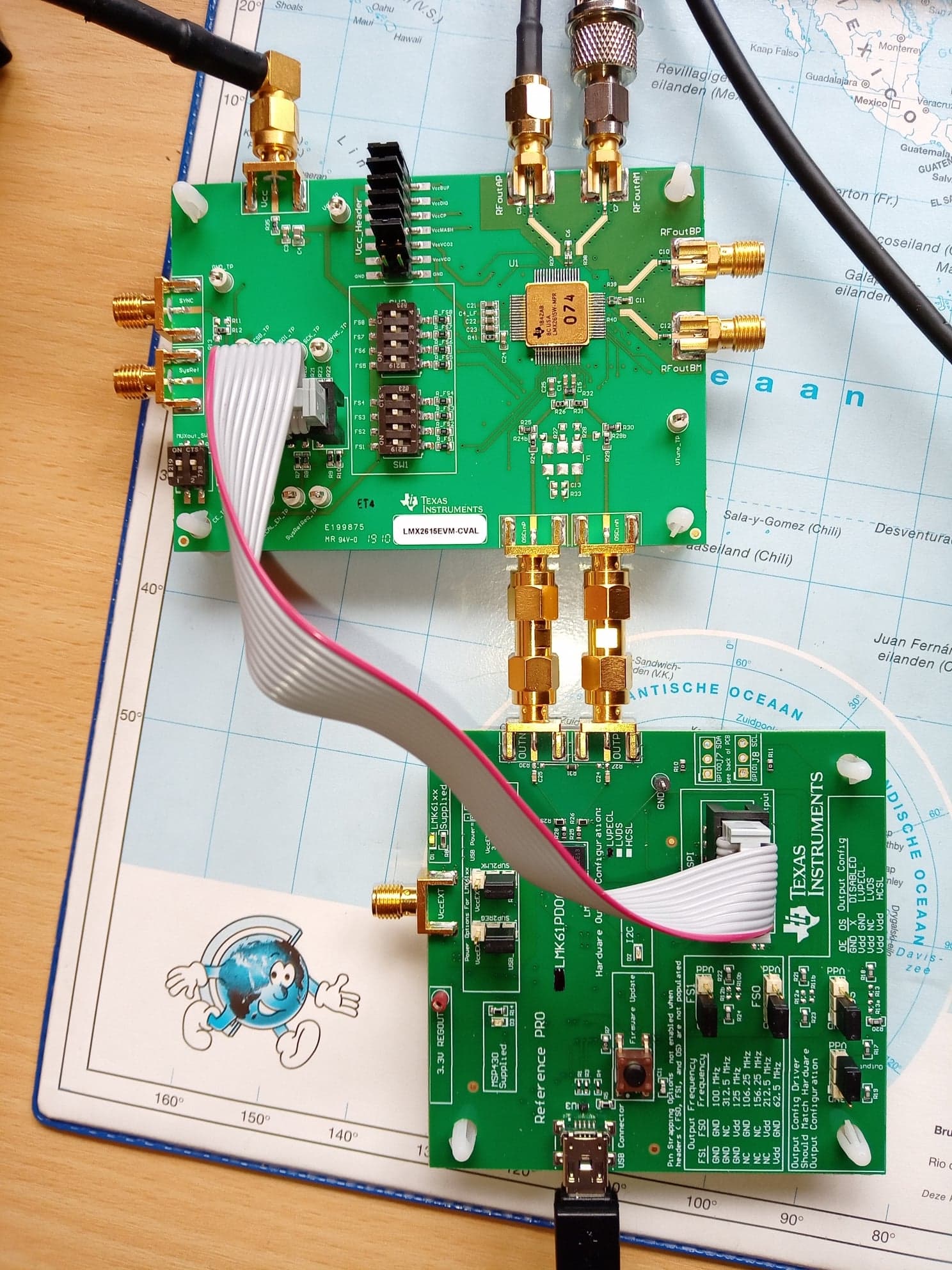
The board is connected to the Reference PRO, which generates correctly 100 MHz (checked via spectrum analyser). The connections to the LMX2615EVM-CVAL are done as described in the manual. The TCIS software is installed (final version). I than load the correct device and additionally set the default values. Normally the lock LED should light up now on the LMX2615EVM-CVAL right? This is not the case. All jumpers are correctly set.

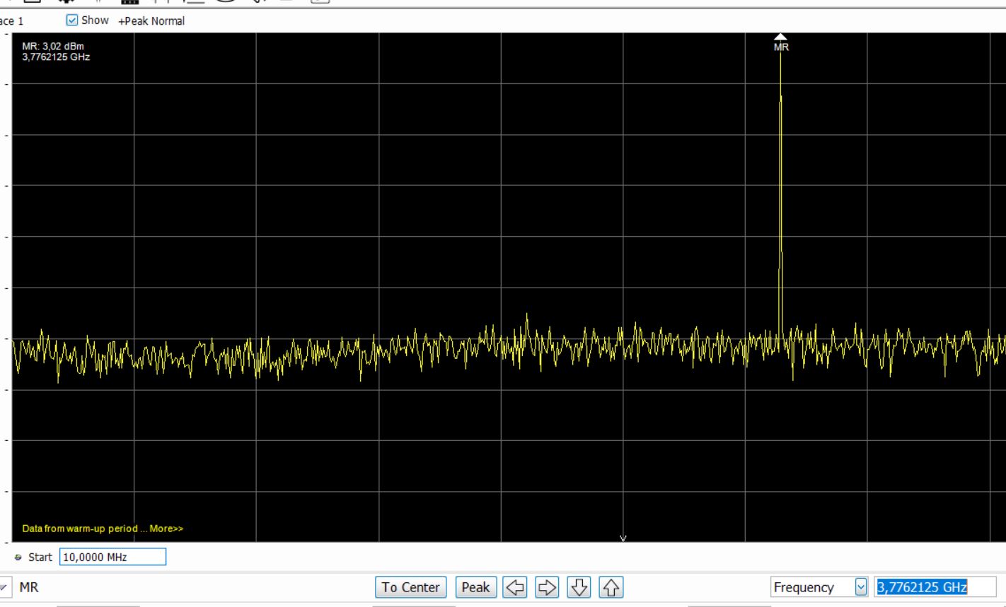
If I change the frequency to, let's say 5 GHz, the board generates a totally different frequency of 3.77 GHz (see printscreen). If I change in small steps, nothing changes. if I change (sometimes) in big steps, suddenly the board generates a signal 500 MHz lower (or higher). It seems the device doesn't respond to the commanded frequency setting.

I already checked the Vtune, and as soon as you send a command, the Vtune gets active.

I really wonder how this problem can be solved.

  • Hello Jurgen,

    I could not see your images, can you try re-attaching them.

    One thing you can try after loading the configuration is toggling the FCAL_EN bit to re-calibrate the PLL. This may help reach the locks state.

    Other debug steps could be:

    -> Ensure that communication is working, try toggling POWERDOWN to see if it is working currectly.

    -> Use an external 100 MHz signal to see if there is an lock.

    Thanks,

    Vibhu


  • Dear Vibhu

    Thanks for your reply.

    Attached you can find the setting in TICS Pro, as well as a printscreen of the spectrum analyser. As you can see I asked for 5 GHz, and the device outputs 3.77 GHz. Changing the frequency in small steps (let's say of a few 10 MHz) doesn't change the output frequency of the device. Even asking to generate 4.9; 4.8; 4.7; 4.6 or 4.5 GHz (or 7.5 GHz) doesn't have any impact. The output stays at 3.77 GHz. Each time I toggle the FCAL_EN and make sure no box is highlighted in red or orange.

    Concerning your proposed steps:

    - I toggled already a few times the FCAL_EN. Each time I implemented a change (switch freq, ...) I toggled this box, without any success.

    - The power down check box works fine. After I toggled it and try to reload the registers the same output frequency appears (not 5 GHz, by 3.77 GHz).

    - Communication should work normally, because the device clearly reacts on my commands 'dfr. the power down command), but not in a good manner. I separately measured the reference Pro, and it clearly puts out a 100 MHz signal.

    Hopefully this helps.

    Many thanks for your effort.

    Best regards

    Jurgen

  • Just for completeness I added a picture of the setup. The upper right SMA connector is connected to a 50 Ohm Dummy load. The left SMA goes to the spectrum analyser. The bottom SMA's are connected to the Reference Pro. The upper most left SMA goes to the power supply. I already try to change the spectrum analyser and dummy load connections, but without any success.

    Best regards

    Jurgen

  • Hi Jurgen,

    Could you remove R32 (close to OSCin pins) and try again? 

    I think we have forgotten to remove R32 in the BOM, since both OSCin pins have 50Ω shunt already.