This thread has been locked.

If you have a related question, please click the "Ask a related question" button in the top right corner. The newly created question will be automatically linked to this question.

LMC555: Negative-Ion generator circuit simplify

Part Number: LMC555

Hi Team,

The customer got a concept about the Negative-Ion generator, such as below chart.

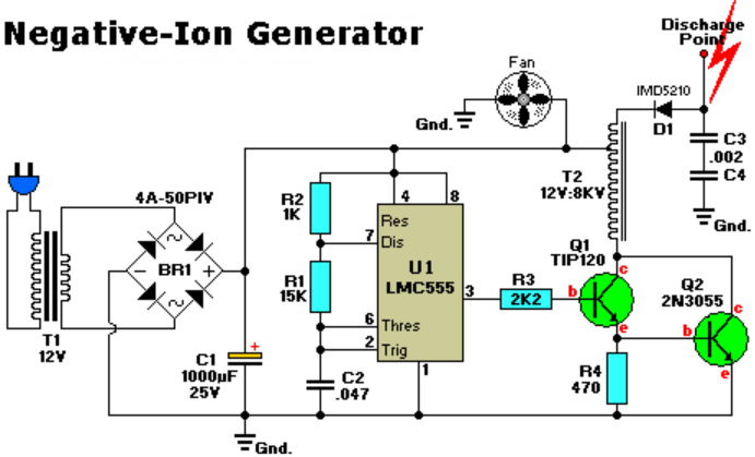
They would like to simplify circuit, because their device is a small portable hand held product.

Do you have any idea or do we has any reference design?

Best regards,

Mike

  • Hello Mike,

    This search term "ion generator site:ti.com" didn't find anything useful. Neither did "tesla coil site:ti.com"

    The concept in the schematic is about as simple as it gets. Build a magnetic field and "open" the circuit to get much higher voltage. The diode and output caps make negative DC voltage at the output for negative ion opposed to both polarities.

    If you would like higher technology for this circuit try this search. "flyback reference design site:ti.com". 

  • Hi team,

    Update the customer spec. They are planing to put 18650(battery) for SYS main power, maybe one or two (series).

    This device is a multi-function portable product, that's why they would like to simplify circuit.

    They hope to reduce Buck and Boost driver for save power and reduce power loss.

    For SYS of MCU power is 3.7V, IO is 1.8V.


    For Negative-Ion generator + Fan power

    I knew that isn't very low, but can we only use one point discharge to metal to produce negative ion? for save power?

    or we are supposed to pick 12V(or more) power for negative ion + fan, we aren't sure that is necessary or not.

    Could you give us a favor?

    Best regards,

    Mike

  • Mike,

    Start with the coil as that is the key component; try to get one that works directly with the battery voltage. Then do the same with the fan.